Tiếng Việt
 日本語
日本語In electronics manufacturing, product reliability depends heavily on assembly quality. Even minor defects in soldering or component placement can lead to costly failures. That’s where the IPC-A-610 Standard comes in. Developed by IPC, this globally recognized standard defines the acceptability criteria for PCB assemblies. It is widely used by OEMs, EMS providers, and quality inspectors to ensure consistent and reliable electronic products. This guide explains what IPC-A-610 is, how it works, and why it is essential in modern PCB assembly.
What Is IPC-A-610 Standard?

Definition of IPC-A-610
The IPC-A-610 Standard, officially known as Acceptability of Electronic Assemblies, is the most widely used inspection standard in the electronics industry. It provides detailed visual criteria to determine whether a printed circuit board assembly (PCBA) meets acceptable quality levels.
Unlike manufacturing standards, IPC-A-610 does not tell you how to build a product. Instead, it defines what a finished, acceptable product should look like. This distinction is critical, especially when multiple suppliers or production lines are involved.
What Does IPC-A-610 Cover?
IPC-A-610 covers nearly every visual aspect of PCB assembly. The standard includes:
- Solder joint evaluation: shape, wetting, coverage, and defects
- Component placement: alignment, polarity, spacing
- PCB condition: cleanliness, surface damage, contamination
- Mechanical integrity: lead conditions, mounting stability
For example, in soldering inspection, the standard specifies how much solder is considered acceptable for different component types. This helps inspectors avoid subjective judgment and ensures consistency across teams.
>>>Read more: ISO Standards for Manufacturing: What OEM Companies Need to Know
Why IPC-A-610 Matters in Electronics Manufacturing
Without a standardized inspection system, quality evaluation becomes inconsistent and dependent on individual inspectors. IPC-A-610 solves this by creating a shared quality language across the entire supply chain.
For OEM companies, this means:
- Clear expectations for suppliers
- Fewer disputes over quality issues
- Better control over outsourced production
For manufacturers, it leads to:
- Reduced rework
- Improved yield rates
- Stronger customer trust
IPC-A-610 Classes Explained (Class 1, 2, 3)
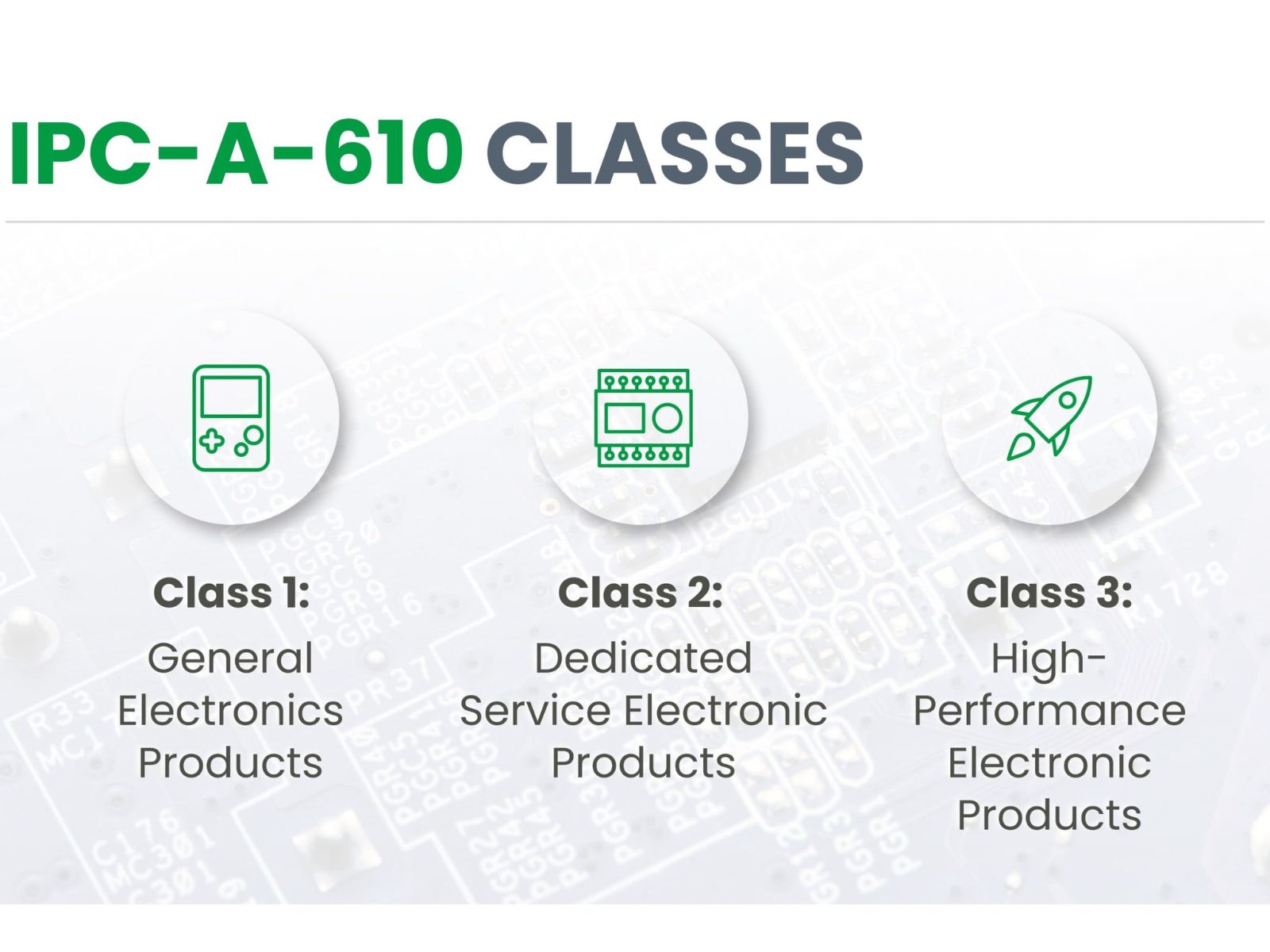
IPC Class 1 – General Electronic Products
Class 1 is the lowest requirement level and applies to products where functionality is the main concern, rather than long-term reliability.
Typical examples include:
- Consumer electronics
- Low-cost devices
In this class, minor cosmetic or structural defects are acceptable as long as the product functions properly. This helps keep manufacturing costs low.
IPC Class 2 – Dedicated Service Electronics
Class 2 represents a balance between performance and cost. Products in this category are expected to operate reliably over time but are not life-critical.
Common applications:
- Industrial equipment
- Communication systems
- Business electronics
Compared to Class 1, inspection criteria are stricter, especially for solder joints and component alignment. Manufacturers must ensure higher consistency and durability.
IPC Class 3 – High-Performance Electronics
Class 3 is the highest level of quality and reliability. It is used for products where failure is not an option.
Examples include:
- Aerospace systems
- Medical devices
- Military electronics
In this class, even small defects that might be acceptable in Class 2 are rejected. Inspection standards are extremely strict, and every detail is carefully evaluated.
Key Differences Between Class 1, 2, and 3
The main difference lies in risk tolerance and reliability requirements. The higher the class, the stricter the inspection criteria.
For OEMs, selecting the correct class is critical. Choosing a lower class to save cost may increase the risk of product failure, while choosing a higher class unnecessarily can increase manufacturing expenses.
>>>Read more: How to Get Quick Turn PCB Assembly for Your Electronics Project
Key Inspection Criteria in IPC-A-610 Standard
Soldering Acceptability Requirements
Solder joints are the most critical connection points in any PCB assembly. IPC-A-610 defines clear criteria for evaluating solder quality, including:
- Proper wetting between solder and pad
- Smooth and uniform fillet shape
- Adequate solder coverage
- Absence of defects such as voids or cracks
For example, a cold solder joint—where the solder does not properly bond—can lead to intermittent electrical connections. IPC-A-610 provides visual references to identify and reject such defects.
Component Mounting and Placement
Proper component placement ensures both electrical performance and mechanical reliability.
IPC-A-610 evaluates:
- Alignment with pads
- Correct orientation and polarity
- Lead positioning and insertion
Misaligned components can cause short circuits or reduce product lifespan. The standard ensures that all components are placed accurately and securely.
PCB Surface and Cleanliness
Cleanliness is often overlooked but plays a critical role in long-term reliability. Residues from flux or contaminants can lead to corrosion or electrical leakage.
IPC-A-610 sets limits on:
- Residue levels
- Foreign object presence
- Surface damage
In high-reliability applications (Class 3), cleanliness requirements are especially strict.
Common Defects Identified by IPC-A-610
Some of the most common defects include:
- Solder bridging: unintended connections between pads
- Insufficient solder: weak electrical connections
- Lifted pads: damaged PCB surfaces
- Tombstoning: uneven component placement
By clearly defining these defects, IPC-A-610 helps inspectors quickly identify issues and take corrective action.
IPC-A-610 vs IPC J-STD-001 – What’s the Difference?
Overview of IPC J-STD-001
IPC J-STD-001 is another important standard that focuses on how to manufacture soldered electronic assemblies.
Inspection vs Process Standards
The key difference is:
- IPC-A-610: Inspection standard (what is acceptable)
- IPC J-STD-001: Process standard (how to achieve it)
Think of IPC-A-610 as the “grading system,” while IPC J-STD-001 is the “instruction manual.”
When to Use Each Standard
In practice, most professional manufacturers use both standards together:
- During production → follow IPC J-STD-001
- During inspection → apply IPC-A-610
This ensures both process control and final product quality.
>>>View details: IPC J-STD-001 vs IPC-A-610: Key Differences in PCB Assembly Standards
Who Should Use IPC-A-610 Standard?
OEM Companies: OEMs use IPC-A-610 to define quality expectations and evaluate suppliers. It helps ensure that outsourced manufacturing meets consistent standards.
EMS / PCB Assembly Manufacturers: For manufacturers, IPC-A-610 is essential for training inspectors and maintaining consistent production quality across batches.
Quality Inspectors & Engineers: Engineers and QA teams rely on IPC-A-610 as a reference for visual inspection and defect classification, making it a core part of quality assurance systems.
Benefits of Using IPC-A-610 in PCB Assembly
Improved Product Quality: Standardized inspection criteria eliminate guesswork and ensure consistent quality across different production lines.
Reduced Manufacturing Defects: Early detection of defects reduces rework, scrap, and production delays.
Better Communication Across Supply Chain: IPC-A-610 provides a common reference point for discussing quality issues between OEMs and manufacturers.
Compliance with Global Standards: Following IPC standards enhances credibility and makes it easier to work with international partners.
IPC-A-610 Certification and Training
IPC-A-610 Certification Levels
Professionals can obtain certifications such as:
- Certified IPC Specialist (CIS)
- Certified IPC Trainer (CIT)
These programs ensure proper understanding and application of the standard.
Why Certification Matters
Certified personnel are more accurate in inspection and better equipped to maintain consistent quality. For OEMs, working with certified partners reduces risk significantly.
How IPC-A-610 Is Applied in Real PCB Assembly Projects

Inspection Process in Manufacturing
IPC-A-610 is applied throughout the production process:
- Incoming inspection
- In-process inspection
- Final inspection
Each stage helps catch defects early and maintain quality control.
Example Use Cases
- Automotive: Requires high reliability and consistency
- Medical: Demands strict compliance with Class 3
- Consumer electronics: Focuses on cost-effective quality
Choosing a PCB Assembly Partner That Follows IPC-A-610
What to Look for in a Manufacturer
- IPC compliance
- Certified inspectors
- Strong QA systems
- Traceability
Questions to Ask Your Supplier
- Do you follow IPC-A-610?
- Which class do you apply?
- Are your inspectors certified?
- How do you handle defects?
Why It Matters for OEM Companies in the US
For US companies outsourcing production, IPC-A-610 ensures consistent quality across international suppliers and reduces operational risks.
Conclusion
The IPC-A-610 Standard is the foundation of PCB assembly inspection worldwide. By defining clear acceptability criteria, it helps manufacturers and OEMs ensure product reliability and consistency. In a global supply chain, adopting IPC-A-610 is not just a technical requirement—it is a strategic advantage that improves quality, reduces risk, and builds trust.
>>>Read more: 7 Mistakes to Avoid When Choosing a Custom PCB Assembly Partner