
 Tiếng Việt
 日本語
日本語
Medical devices are expected to perform flawlessly in environments where even a minor failure can have serious consequences. Unlike consumer electronics, medical equipment often operates in life-critical situations, requiring a much higher level of reliability, safety, and regulatory compliance. Whether you’re developing a wearable health monitor, diagnostic imaging equipment, infusion pump, or patient monitoring system, the success of your product begins long before manufacturing—it starts with medical device PCB design.
A well-designed printed circuit board (PCB) not only ensures stable electrical performance but also simplifies regulatory approval, improves manufacturing yield, and reduces long-term maintenance risks. Poor PCB design, on the other hand, can lead to electromagnetic interference (EMI), thermal failures, product recalls, or costly redesigns during certification. This guide explores the 12 critical requirements every engineer, product designer, and OEM should understand when designing PCBs for medical electronics. It also explains how early collaboration with an experienced manufacturing partner can help transform a compliant design into a reliable, production-ready product.
What Is Medical Device PCB Design?
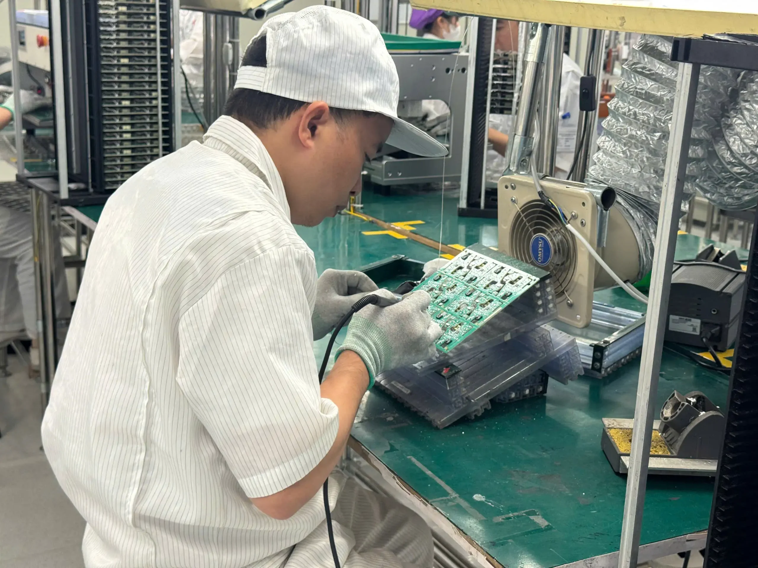
Medical device PCB design is the process of developing printed circuit boards specifically for healthcare and life science applications. Unlike standard PCB design, it emphasizes patient safety, long-term reliability, electromagnetic compatibility, and compliance with strict international regulations.
A medical PCB is more than an electrical interconnection platform. It serves as the foundation for critical electronic systems that monitor, diagnose, or treat patients. Because these devices often operate continuously or in safety-sensitive environments, every design decision—from material selection to PCB layout—must support consistent and predictable performance.
Typical medical PCB applications include:
- Patient monitoring systems
- ECG and EEG equipment
- Portable diagnostic devices
- Infusion pumps
- Surgical instruments
- Medical imaging equipment
- Laboratory analyzers
- Wearable medical devices
- Remote healthcare monitoring systems
As medical electronics continue to become smaller, smarter, and more connected, PCB designs must also accommodate higher component density, faster signal speeds, wireless communication, and lower power consumption without compromising reliability.
Related: Learn how a reliable manufacturing partner supports the transition from design to production through Medical Device PCBA and Prototype PCB Assembly. (Internal links to relevant SHDC service pages.)
Why Medical Device PCB Design Is More Challenging Than Standard PCB Design
Many engineers assume that designing a medical PCB is simply a matter of using higher-quality components. In reality, medical electronics involve an entirely different engineering philosophy.
Instead of focusing primarily on cost or consumer features, medical PCB design prioritizes risk reduction, regulatory compliance, patient safety, and product longevity.
| Standard PCB Design | Medical Device PCB Design |
|---|---|
| Consumer-focused | Patient safety-focused |
| Moderate reliability | Extremely high reliability |
| Cost optimization | Risk mitigation |
| Short product lifecycle | Long product lifecycle |
| Basic quality control | Full traceability |
| Limited regulatory requirements | Strict regulatory compliance |
Several factors make medical PCB design significantly more demanding.
Patient safety comes first
Any electrical fault, signal interruption, or thermal issue could directly affect patient diagnosis or treatment. Designers must carefully consider electrical isolation, leakage current, grounding, and redundant safety mechanisms throughout the PCB layout.
Regulatory compliance is mandatory
Medical devices are regulated by organizations such as the U.S. Food and Drug Administration (FDA) and must comply with internationally recognized standards including IEC 60601, ISO 13485, and various IPC specifications.
Rather than treating compliance as a final testing step, successful manufacturers integrate these requirements into the PCB design process from the very beginning.
Reliability expectations are significantly higher
Unlike consumer electronics that may be replaced every few years, medical devices often remain in service for ten years or longer.
This demands:
- Stable electrical performance
- Long component availability
- High mechanical durability
- Resistance to humidity and temperature variation
- Excellent solder joint reliability
Manufacturing considerations become more important
A technically functional PCB design is not necessarily manufacturable.
By incorporating Design for Manufacturability (DFM) and Design for Testability (DFT) early in development, engineers can reduce production defects, improve yields, and shorten time to market.
Related Reading: Explore our guides on Design for Manufacturing (DFM) and Design for Testability (DFT) to understand how design decisions directly influence manufacturing quality. (Internal links.)
Why Early PCB Design Decisions Affect the Entire Product Lifecycle
Many product teams view PCB design as an isolated engineering task. In reality, every design decision influences nearly every downstream stage of the product lifecycle, including:
- Component sourcing
- Prototype assembly
- Functional testing
- EMC certification
- Regulatory approval
- Manufacturing yield
- Product reliability
- Field maintenance
- Product revisions
For example, selecting an obsolete component may delay production by several months. Similarly, insufficient spacing between high-voltage traces may require a complete PCB redesign after failing electrical safety testing.
These issues are significantly easier—and far less expensive—to resolve during the design phase than after production tooling has begun.
This is why experienced OEMs increasingly involve their EMS partners early in product development. Engineering reviews, DFM analysis, and prototype validation help identify manufacturability issues before they become costly production problems.
12 Critical Requirements for Medical Device PCB Design
Designing a PCB for medical electronics requires much more than creating a functional circuit. Every layout decision can affect product safety, regulatory approval, manufacturing yield, and long-term reliability. Below are the twelve most important design requirements engineers should address before moving into prototype fabrication or mass production.
1. Design for Patient Safety
Patient safety is the primary objective of every medical device. Unlike consumer electronics, medical equipment often operates in direct contact with patients or supports life-critical functions. Even a minor electrical fault could result in inaccurate diagnoses, interrupted treatment, or patient injury.
Therefore, safety requirements should be incorporated into the PCB architecture from the earliest design stage rather than addressed during certification testing.
Key design considerations include:
- Maintaining adequate creepage and clearance distances for high-voltage circuits.
- Proper electrical isolation between patient-connected circuits and mains power.
- Designing reliable protective grounding systems.
- Minimizing leakage current.
- Preventing accidental short circuits caused by contamination or moisture.
For example, patient-monitoring equipment and diagnostic systems typically require reinforced isolation barriers between sensitive analog front-end circuits and power sections. Ignoring these requirements can lead to failure during electrical safety testing under IEC 60601, often resulting in expensive PCB redesigns.
Beyond regulatory compliance, designing with safety in mind also improves product reliability throughout its service life.
Best Practice
Perform electrical safety reviews before PCB layout begins, not after routing is complete. This significantly reduces redesign cycles during certification.
External Reference
- FDA Design Controls for Medical Devices
- IEC 60601 Medical Electrical Equipment Standards
2. Design for Regulatory Compliance from Day One
One of the most common mistakes in medical product development is treating regulatory compliance as the responsibility of the quality department.
In reality, many regulatory requirements originate during PCB design.
Medical electronics are typically expected to comply with standards such as:
| Standard | Purpose |
|---|---|
| IEC 60601 | Electrical safety and essential performance |
| ISO 13485 | Medical device quality management |
| IPC-A-610 Class 3 | Highest PCB assembly workmanship requirements |
| IPC-2221 | PCB design standard |
| IPC-6012 Class 3 | High-reliability PCB fabrication |
| FDA Design Controls (21 CFR Part 820) | Design documentation and verification |
Designing with these standards in mind helps avoid common issues such as:
- Insufficient electrical spacing
- Poor trace routing
- Inadequate documentation
- Improper material selection
- Difficult inspection or testing
For OEMs targeting the U.S. market, integrating compliance requirements early can significantly shorten certification timelines while reducing engineering change orders (ECOs).
Related Reading: Learn more about IPC standards and IPC-A-610 to understand how industry requirements influence PCB quality and assembly. (Internal links to your IPC-related articles.)
3. Select High-Reliability Components
A PCB can only be as reliable as the components installed on it.
Medical devices frequently operate continuously for thousands of hours. Consequently, component selection should prioritize reliability over purchase cost.
When evaluating components, engineers should consider:
- Long product lifecycle availability
- Manufacturer reputation
- Operating temperature range
- Mean Time Between Failures (MTBF)
- Moisture sensitivity level (MSL)
- Automotive or medical-grade qualification when appropriate
- Component obsolescence risk
Using discontinued or difficult-to-source components may introduce unnecessary redesigns later in production.
Many EMS providers also recommend establishing approved alternative components during the design phase. This strategy minimizes supply chain disruptions without requiring PCB redesign.
For complex medical electronics, maintaining a robust Approved Vendor List (AVL) is equally important for long-term production stability.
4. Choose the Right PCB Materials

PCB material selection directly influences thermal stability, electrical performance, mechanical durability, and manufacturing reliability.
Although standard FR-4 materials are suitable for many medical devices, higher-performance applications may require specialized laminates.
Common material options include:
| Material | Typical Applications |
|---|---|
| Standard FR-4 | General medical electronics |
| High Tg FR-4 | High-temperature environments |
| Polyimide | Flexible medical devices |
| Rogers | High-frequency RF medical systems |
| Flexible PCB Materials | Wearables and implantable accessories |
Material selection should consider:
- Operating temperature
- Sterilization processes
- Moisture resistance
- Mechanical stress
- Signal frequency
- Long-term reliability
For wearable healthcare devices, flexible PCBs can improve durability while reducing product size.
Meanwhile, imaging equipment and RF diagnostic devices may require low-loss materials to maintain signal integrity.
Early collaboration with your PCB manufacturer can help identify materials that meet both performance and manufacturing requirements without unnecessarily increasing production costs.
5. Maintain Excellent Signal Integrity
Medical devices often process extremely small electrical signals. Even minimal noise can affect measurement accuracy.
Applications such as ECG, EEG, ultrasound, and patient monitoring require precise analog signal processing alongside increasingly complex digital communication.
PCB layout should therefore minimize signal degradation by applying sound signal integrity practices.
Recommended techniques include:
- Controlled impedance routing
- Continuous ground planes
- Differential pair routing
- Short signal paths
- Proper return current paths
- Separation of analog and digital circuits
- Appropriate decoupling capacitor placement
Engineers should also avoid unnecessary vias on sensitive high-speed signals whenever possible.
Simulation tools can further verify signal quality before prototype fabrication, reducing development risk.
6. Control EMI and EMC Early in the Design Process
Electromagnetic interference (EMI) remains one of the leading causes of medical device certification failures.
Many PCB designs perform well during functional testing but fail electromagnetic compatibility (EMC) evaluation because interference was not considered during layout.
Common sources of EMI include:
- Switching power supplies
- High-speed digital interfaces
- Wireless communication modules
- Poor grounding
- Inadequate shielding
To improve EMC performance, designers should:
- Use solid ground planes.
- Separate noisy power circuits from sensitive analog circuits.
- Minimize loop areas.
- Add proper filtering where required.
- Place decoupling capacitors close to IC power pins.
- Route differential pairs together.
- Follow return current paths carefully.
In addition, enclosure design and PCB layout should be developed together whenever possible.
Many EMC issues cannot be completely solved by adding filters after the PCB has already been manufactured.
Tip: Performing an EMC design review before prototype fabrication is significantly less expensive than redesigning a PCB after failing compliance testing.
7. Optimize Thermal Management
Heat is one of the leading causes of premature electronic failure. In medical devices, excessive temperatures can reduce component lifespan, affect measurement accuracy, and compromise overall system reliability. This is particularly important for equipment that operates continuously, such as patient monitors, ventilators, imaging systems, and laboratory analyzers.
Thermal management should therefore be considered during PCB layout—not after prototype testing.
Key design strategies include:
- Position heat-generating components away from sensitive analog circuits.
- Use thermal vias beneath power components to improve heat transfer.
- Increase copper area for high-current traces.
- Distribute heat sources evenly across the PCB.
- Select PCB materials with appropriate thermal characteristics.
- Design adequate airflow if the enclosure allows forced or natural convection.
For high-power medical electronics, engineers often perform thermal simulation before fabrication to identify potential hot spots and optimize component placement.
Engineering Tip: A PCB that passes functional testing at room temperature may still fail long-term reliability testing if thermal dissipation is not properly addressed.
8. Apply Design for Manufacturability (DFM)
A PCB that functions perfectly in simulation may still be difficult—or expensive—to manufacture.
Design for Manufacturability (DFM) focuses on creating PCB layouts that improve assembly efficiency, reduce defects, and increase production yield. By considering manufacturing constraints early in the design process, engineers can minimize costly redesigns and shorten time to market.
Key DFM considerations include:
- Maintain adequate spacing between components.
- Follow recommended pad and footprint dimensions.
- Design proper solder mask openings.
- Include fiducial marks for automated optical alignment.
- Optimize panelization for efficient SMT assembly.
- Avoid placing components too close to PCB edges.
- Design with automated assembly equipment in mind.
Early DFM reviews can identify issues before fabrication begins, preventing common production problems such as solder bridging, tombstoning, insufficient solder joints, or component placement errors.
Related Reading: Learn how Design for Manufacturing (DFM) improves production yield and reduces manufacturing costs. (Internal link to your DFM article.)
9. Design for Testability (DFT)
Medical devices require rigorous verification before they can enter the market. PCB design should therefore support efficient inspection and testing throughout both prototype and mass production.
Design for Testability (DFT) makes it easier to identify manufacturing defects, validate functionality, and improve product quality.
Recommended DFT practices include:
- Provide accessible test points for critical signals.
- Allow in-circuit testing (ICT) where applicable.
- Support flying probe testing for low-volume production.
- Design for functional testing (FCT).
- Include programming interfaces for firmware loading.
- Consider boundary scan (JTAG) for complex digital systems.
Effective DFT reduces troubleshooting time, improves production efficiency, and ensures consistent product quality.
For medical electronics, comprehensive testing is particularly important because hidden defects may only appear after prolonged operation or under specific environmental conditions.
Related Reading: Discover how Design for Testability (DFT) helps manufacturers improve quality assurance and reduce production risks. (Internal link to your DFT article.)
10. Design for Reliability in Harsh Operating Conditions
Medical devices are often exposed to environments that are far more demanding than typical consumer electronics.
Depending on the application, PCBs may experience:
- Continuous 24/7 operation
- High humidity
- Frequent cleaning and disinfection
- Mechanical shock during transportation
- Vibration in mobile medical equipment
- Temperature fluctuations
- Electrostatic discharge (ESD)
PCB designs should account for these conditions by selecting appropriate materials, applying protective coatings when necessary, and ensuring robust solder joint reliability.
For portable medical devices, designers should also evaluate connector durability, battery performance, and mechanical reinforcement around frequently stressed areas.
Long-term reliability testing—including thermal cycling, vibration testing, and environmental stress screening—can further validate design robustness before mass production.
11. Ensure Complete Documentation and Traceability

Medical device manufacturing demands far more documentation than standard electronics production. Accurate records are essential for regulatory compliance, quality management, and future product maintenance.
Essential documentation typically includes:
- Schematic diagrams
- PCB layout files
- Gerber files
- Bill of Materials (BOM)
- Assembly drawings
- Pick-and-place files
- Test procedures
- Revision history
- Engineering Change Orders (ECOs)
Equally important is component traceability. Manufacturers should be able to identify:
- Component supplier
- Lot number
- Manufacturing date
- Assembly batch
- Test results
Comprehensive traceability enables faster root cause analysis, simplifies product recalls if necessary, and supports compliance with medical quality management systems.
For OEMs, maintaining well-organized documentation also streamlines future product revisions and regulatory audits.
12. Collaborate with Your PCB Manufacturer Early
One of the most effective ways to improve medical PCB quality is to involve your manufacturing partner during the design phase.
Experienced EMS providers can review PCB layouts before fabrication and identify potential manufacturing risks that may not be apparent during schematic design.
Early collaboration offers several advantages:
- DFM recommendations to improve manufacturability
- Component sourcing advice
- Material selection guidance
- Cost optimization opportunities
- Prototype feasibility assessment
- Faster transition to mass production
- Reduced engineering change orders
Rather than waiting until the design is finalized, many OEMs now engage their manufacturing partner during PCB layout to optimize production efficiency from the beginning.
This collaborative approach often results in higher yields, shorter development cycles, and lower overall project costs.
Common Medical PCB Design Mistakes to Avoid
Even experienced engineering teams can overlook critical design considerations. Avoiding these common mistakes can significantly improve product reliability and reduce certification delays.
Ignoring regulatory requirements
Treating standards such as IEC 60601 or IPC Class 3 as post-design considerations often leads to costly redesigns.
Poor grounding strategy
Improper grounding increases susceptibility to noise, EMC failures, and unstable analog measurements.
Inadequate thermal design
Overheating shortens component lifespan and may affect measurement accuracy.
Choosing components based solely on cost
Low-cost components may introduce long-term supply chain risks or fail to meet reliability requirements.
Insufficient testability
Without proper test points and validation strategies, manufacturing defects become more difficult to detect.
Delaying DFM reviews
Manufacturing issues identified after prototype fabrication are significantly more expensive to resolve.
From PCB Design to Medical Device Manufacturing
A successful medical product requires close coordination between design engineering and manufacturing.
The typical development process includes:
- Product requirements definition
- Schematic design
- PCB layout
- Design verification
- DFM and DFT review
- Prototype fabrication
- PCB assembly
- Functional testing
- Regulatory validation
- Pilot production
- Mass production
Each stage builds upon the previous one, making early design decisions critical to overall project success.
Related Reading: Explore our guides on Prototype PCB Assembly, Turnkey PCB Assembly, and PCB Assembly Services to learn how professional EMS partners support every stage of production. (Internal links.)
How SHDC Supports Medical Device Electronics Manufacturing

Although product design remains the responsibility of the OEM, choosing the right manufacturing partner can significantly influence the quality and success of a medical electronics project.
At SHDC, our engineering team works closely with customers to evaluate manufacturability before production begins. Through early DFM and DFT reviews, we help identify potential assembly challenges, optimize PCB layouts for manufacturing, and reduce production risks.
Our capabilities include:
- Prototype and low-volume PCB assembly
- High-mix, low-volume manufacturing
- SMT and THT assembly
- Box build integration
- AOI inspection and SPI process control
- Functional testing support
- Component sourcing assistance
- Full production traceability
- IPC-compliant manufacturing processes
Whether you’re developing a new wearable medical device or preparing an existing product for mass production, early collaboration can help improve manufacturing efficiency while maintaining the reliability expected of medical electronics.
Ready to bring your medical electronics project to production? Contact SHDC to discuss your PCB assembly requirements, request a DFM review, or receive a quotation for your next prototype or production build. Contact SHDC
Frequently Asked Questions (FAQ)
What makes medical device PCB design different from standard PCB design?
Medical PCB design prioritizes patient safety, regulatory compliance, long-term reliability, electromagnetic compatibility (EMC), and traceability. These requirements are significantly more stringent than those for consumer electronics.
Which standards are most important for medical PCB design?
Common standards include IEC 60601 for electrical safety, ISO 13485 for quality management, IPC-A-610 Class 3 for assembly quality, IPC-2221 for PCB design, and FDA Design Controls for medical device development.
Can standard FR-4 materials be used in medical devices?
Yes. Standard FR-4 is suitable for many medical applications. However, high-frequency systems, wearable devices, or products exposed to elevated temperatures may require specialized PCB materials.
Why is DFM important for medical electronics?
DFM helps identify manufacturing challenges early, improving production yield, reducing assembly defects, lowering costs, and shortening development timelines.
When should an EMS partner be involved in the design process?
Ideally, manufacturers should be involved before PCB fabrication begins. Early engineering reviews enable DFM optimization, improve manufacturability, and reduce costly redesigns.
