
 Tiếng Việt
 日本語
日本語
Design for Manufacturing is one of the most important steps between product design and scalable electronics production. For OEMs, especially U.S. companies working with overseas EMS partners, DFM helps identify design, sourcing, assembly, and testing risks before they become expensive production problems. In electronics manufacturing, a product may work well as a prototype but still create challenges during SMT assembly, DIP insertion, inspection, functional testing, or final assembly. A structured DFM review helps OEM teams prepare the design for real production conditions.
What Is Design for Manufacturing?

Design for Manufacturing, commonly called DFM, is the process of designing a product so it can be manufactured efficiently, consistently, and at the required quality level. Instead of reviewing only whether the product works, DFM asks a more production-focused question: can this product be built repeatedly at scale without unnecessary defects, rework, delays, or cost?
For electronics OEMs, Design for Manufacturing usually covers PCB layout, component selection, BOM accuracy, soldering process, SMT placement, through-hole assembly, inspection access, test strategy, fixture planning, and final packaging requirements.
DFM is especially important in PCBA manufacturing because small decisions in the design stage can affect the entire production process. Pad size, component spacing, connector position, test point access, thermal design, and part availability can all influence quality, yield, and lead time.
Why Design for Manufacturing Matters for Electronics OEMs
For many OEMs, the biggest manufacturing risks do not appear during early product development. They appear when the product moves from prototype to pilot build, or from pilot build to mass production.
A prototype can be hand-assembled, manually adjusted, or tested one unit at a time. Mass production is different. The design must work with solder paste printing, pick-and-place machines, reflow ovens, wave soldering, AOI inspection, ICT or FCT testing, assembly fixtures, packaging flow, and supply chain requirements.
Without DFM, OEMs may face:
- PCB redesign after fabrication
- Solder bridging or tombstoning
- Component misalignment
- Poor access for test probes
- Long-lead or obsolete components
- Low first-pass yield
- Rework and scrap
- Delayed product launch
- Higher total production cost
A good DFM process reduces these risks before the production line starts. It also improves communication between the OEM engineering team and the EMS partner.
For companies preparing a new product, DFM should be connected with NPI in electronics manufacturing, pilot production, and production readiness planning. When these steps are aligned early, the transition from design to manufacturing becomes more predictable.
DFM vs DFA vs DFT vs DFX
Design for Manufacturing is often discussed together with DFA, DFT, and DFX. These concepts are related, but each has a different focus.
| Term | Full Name | Main Focus | Electronics Example |
|---|---|---|---|
| DFM | Design for Manufacturing | Can the product be manufactured efficiently? | PCB spacing, panelization, solderability |
| DFA | Design for Assembly | Can the product be assembled easily? | Connector access, screw position, housing fit |
| DFT | Design for Testability | Can the product be tested reliably? | Test points, ICT access, FCT procedure |
| DFX | Design for Excellence | Broader design optimization | Cost, quality, reliability, serviceability |
In electronics, these areas often overlap. For example, moving a connector may improve assembly access, reduce soldering risk, and make functional testing easier at the same time. That is why OEMs should treat DFM as part of a broader production-readiness strategy, not as a single checklist at the end of design.
How DFM Applies to Electronics Manufacturing
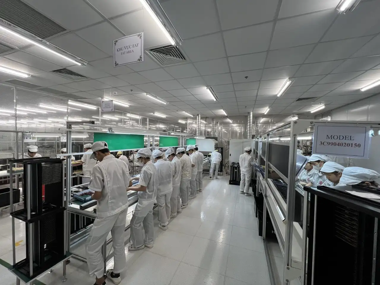
PCB Layout Review
PCB layout is one of the most important areas in Design for Manufacturing. A layout that works electrically may still create problems for assembly, inspection, or testing.
A DFM review should check component spacing, pad design, board edge clearance, fiducial marks, via placement, copper balance, thermal relief, panelization, and solder mask clearance. For complex boards, the manufacturer should also review whether the design is suitable for the selected SMT line and inspection process.
PCB size and panelization are also important. If the board is too small, too thin, or has unusual edges, it may require special fixtures or carriers. If the board is not designed with production handling in mind, it can slow down the SMT assembly process.
Component Selection and BOM Review
The bill of materials is another major part of DFM. Even if the PCB layout is strong, production can still be delayed if the BOM includes parts with long lead times, unclear part numbers, limited suppliers, or obsolete components.
A proper DFM review should check:
- Manufacturer part numbers
- Package sizes
- Approved alternatives
- Component lifecycle status
- MOQ and lead time
- Supplier availability
- Polarity and orientation requirements
- Special handling requirements
For U.S. OEMs sourcing overseas, BOM clarity is especially important. The EMS partner needs complete and accurate information to quote the project, source parts, plan assembly, and avoid procurement delays. This is also why a complete PCB assembly quote should include not only the Gerber files, but also the BOM, pick-and-place file, test requirements, and volume forecast.
SMT Assembly Considerations
SMT is widely used in modern electronics because it supports compact PCB design and high-speed assembly. However, SMT also requires careful design control.
During a DFM review, the EMS partner should evaluate whether components are suitable for pick-and-place, whether placement orientation is clear, whether solder paste printing is reliable, and whether the reflow process can support the board design.
Common SMT-related DFM issues include:
- Insufficient component spacing
- Uneven pad design
- Poor thermal balance
- Incorrect land pattern
- Difficult component orientation
- Lack of fiducials
- Components placed too close to the board edge
These issues can lead to defects such as solder bridging, insufficient solder, component shift, tombstoning, or open joints. For more detailed production risk analysis, OEMs can also review common PCB assembly defects before finalizing the design.
DIP and Through-Hole Assembly Considerations
Not every component can be placed using SMT. Connectors, transformers, large capacitors, switches, and mechanical components may require through-hole or DIP assembly.
A DFM review should check hole size, lead length, component stability, soldering method, clearance around tall components, and whether the board is suitable for wave soldering or selective soldering.
The comparison between SMT vs through-hole is important because each process affects cost, reliability, board layout, and production flow. SMT is efficient for compact, high-volume products, while through-hole assembly is often used when stronger mechanical support is needed.
Testing and Inspection Requirements
DFM should also include testing and inspection. A product that is easy to assemble but difficult to test can still create major production risks.
OEMs should define the test strategy early. Depending on the product, this may include AOI, SPI, ICT, FCT, visual inspection, aging test, high-voltage test, or custom functional testing. Test points must be accessible, fixture requirements must be understood, and pass/fail criteria should be clearly documented.
For PCBA projects, automated optical inspection can help detect placement and soldering issues, while in-circuit testing and functional testing help verify electrical performance. The earlier these requirements are considered, the easier it is to design a board that can be tested consistently during production.
Practical DFM Checklist for Electronics OEMs
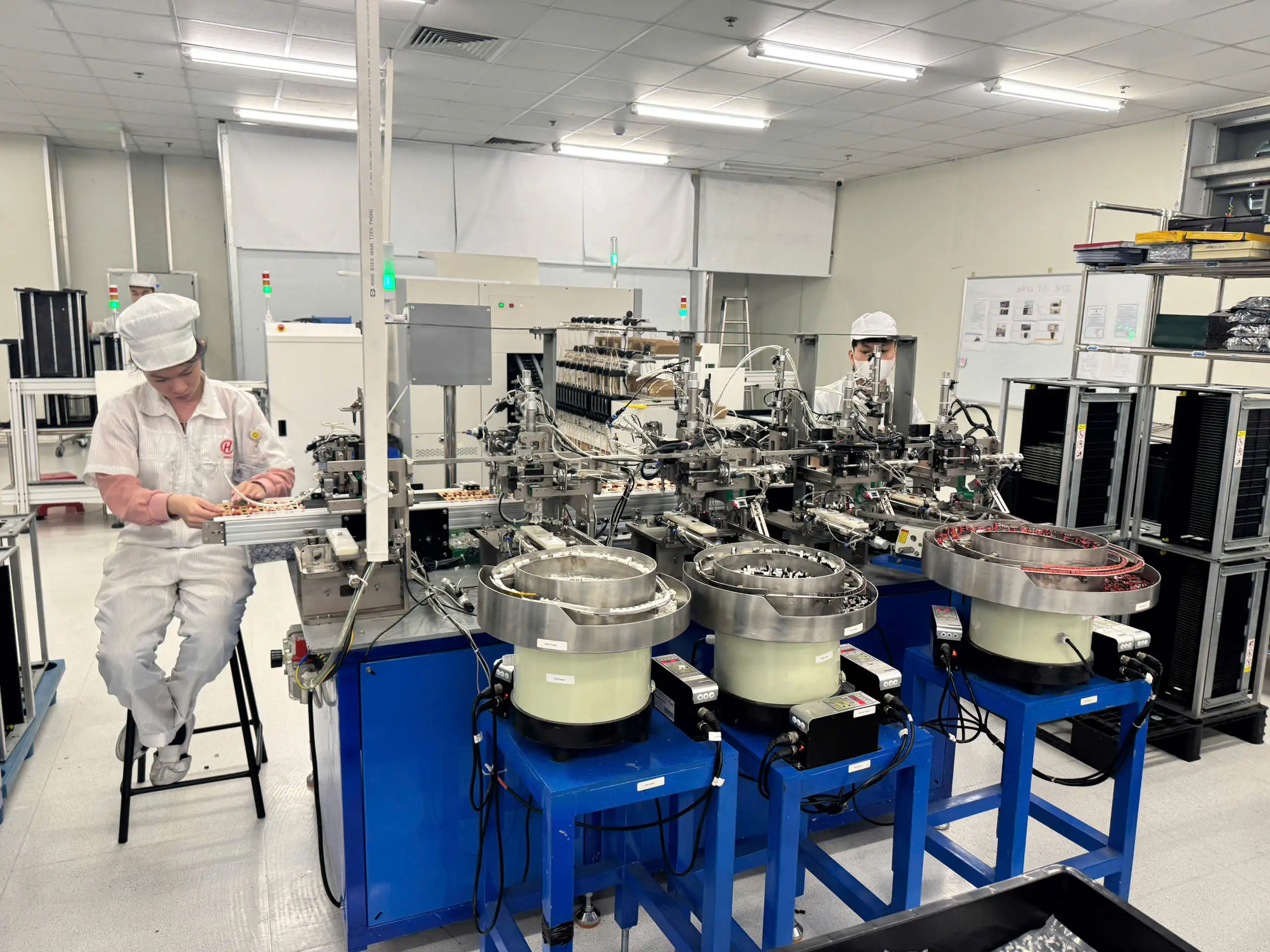
A DFM checklist helps OEMs prepare design files and reduce avoidable production questions. Before sending a project to an EMS partner, review the following areas.
PCB Design Checklist
- Are PCB dimensions suitable for manufacturing equipment?
- Are components placed with enough clearance?
- Are fiducial marks included?
- Are critical components away from board edges?
- Is the panelization strategy clear?
- Are thermal-sensitive parts placed carefully?
- Are polarity markings visible?
- Is the solder mask design appropriate?
BOM Checklist
- Is the BOM complete and updated?
- Are manufacturer part numbers included?
- Are approved alternatives listed?
- Are obsolete or risky components removed?
- Are long-lead parts identified?
- Are special sourcing requirements documented?
Assembly Checklist
- Are SMT and DIP steps clearly separated?
- Are tall components positioned correctly?
- Are connectors easy to access?
- Are manual assembly steps minimized?
- Are mechanical parts compatible with the enclosure?
- Are cable routing and final assembly requirements clear?
Testing Checklist
- Are test points accessible?
- Is ICT or FCT required?
- Are functional test procedures available?
- Are pass/fail criteria clearly defined?
- Are firmware loading or programming instructions included?
- Are inspection standards agreed before production?
Documentation Checklist
OEMs should prepare Gerber files, BOM, pick-and-place file, assembly drawing, PCB specification, test procedure, firmware instructions, quality requirements, packaging requirements, and target production volume.
Clear documentation reduces the chance of miscommunication and helps the EMS partner provide faster, more accurate feedback.
Common DFM Mistakes That Delay Production
Designing Only for Prototype Builds
A common mistake is designing only for a prototype. In early development, engineers may focus on electrical function and ignore manufacturability. This can work for a few hand-built boards, but it often fails when the product moves to automated assembly.
Production design should consider line setup, soldering process, inspection flow, test fixtures, packaging, and repeatability from the beginning.
Incomplete BOM Data
Missing part numbers, unclear specifications, or unavailable components can delay the entire production schedule. A strong BOM should include manufacturer part number, description, package type, quantity, approved alternatives, and sourcing notes.
Poor Test Access
If test points are missing or blocked, ICT and functional testing become more difficult. This can increase testing time, require manual workarounds, or reduce defect detection.
Ignoring Process Limitations
Every manufacturing process has practical limitations. PCB thickness, component size, board dimensions, soldering method, fixture design, and inspection capability all matter. OEMs should work with the EMS partner early to understand these limits before releasing the design.
Late Engineering Changes
When manufacturability issues are found late, OEMs may need to create Engineering Change Orders, revise PCB files, update BOMs, revalidate samples, and delay production. DFM helps reduce the number of late-stage changes by identifying risks earlier.
Design for Manufacturing Process: From Review to Production
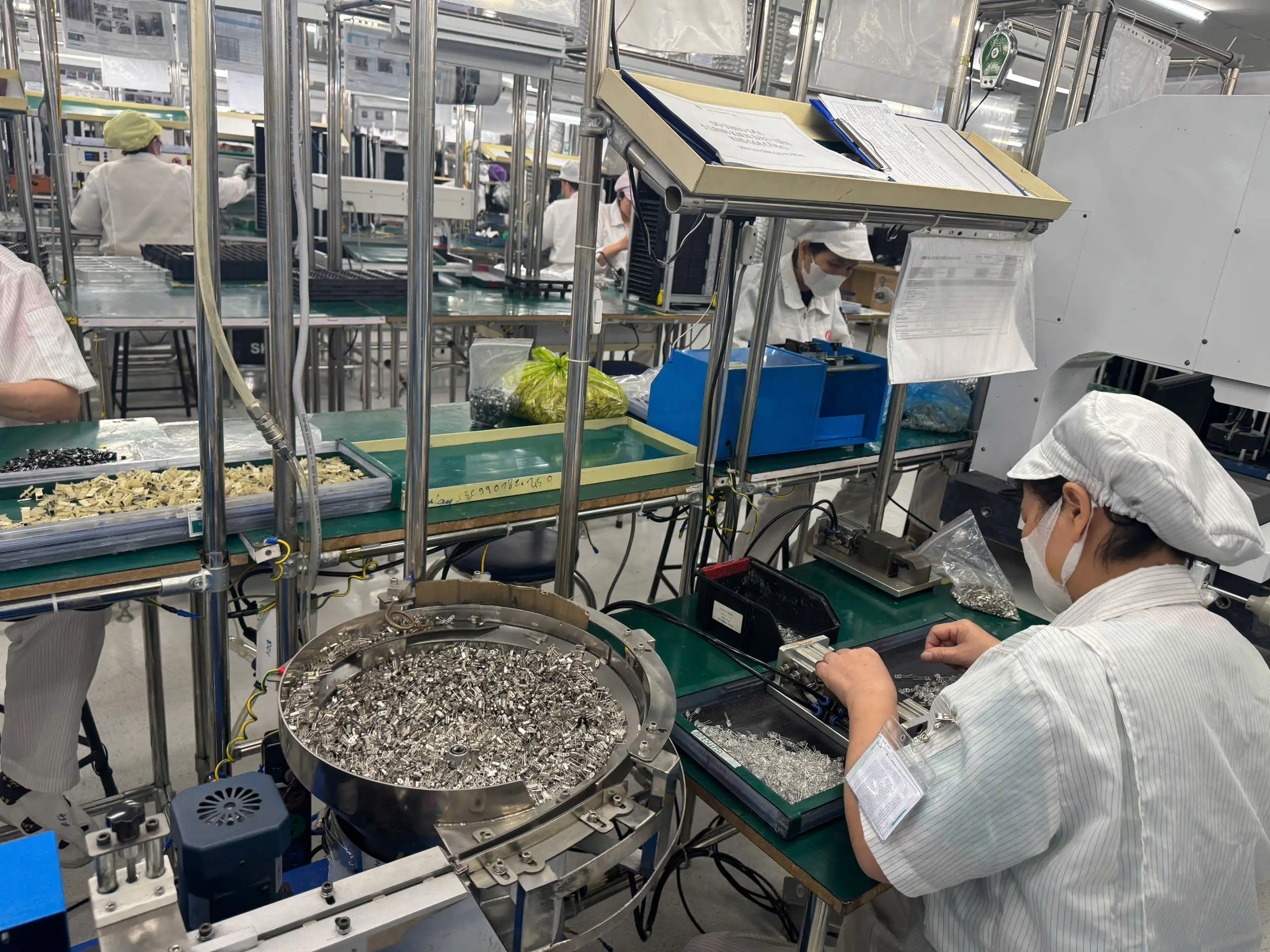
A practical DFM process usually includes six steps.
Step 1: Initial File Review
The EMS partner reviews Gerber files, BOM, pick-and-place data, assembly drawings, product specifications, and test requirements.
Step 2: Manufacturability Feedback
The manufacturer provides feedback on PCB layout, component selection, assembly process, soldering risks, inspection access, testability, and documentation gaps.
Step 3: Design Update
The OEM updates the design based on feedback. This may include layout changes, BOM corrections, test point adjustments, or mechanical changes.
Step 4: Prototype or Pilot Build
A prototype or pilot run validates the production process. This stage helps identify practical issues that may not be visible in design files.
Step 5: Testing and Quality Review
The product goes through inspection and testing. Results from AOI, ICT, FCT, visual inspection, or aging tests can be used to improve the process before mass production.
Step 6: Production Readiness
The design is ready for mass production when engineering, supply chain, assembly, testing, quality control, and packaging requirements are aligned. OEMs can use a Production Readiness Checklist to confirm the project is prepared before scaling.
What OEMs Should Prepare Before a DFM Review
Before requesting a DFM review, OEMs should prepare:
- Product specification
- Gerber files
- BOM
- Pick-and-place file
- Assembly drawing
- Mechanical files if enclosure or box build is required
- Target production volume
- Quality requirements
- Testing requirements
- Packaging requirements
- Launch timeline
- Market or compliance requirements
The more complete the input data, the more useful the DFM feedback will be. Incomplete files may still allow a preliminary review, but the EMS partner may not be able to identify all production risks.
How an EMS Partner Supports Design for Manufacturing
An experienced EMS partner does more than assemble boards. The right partner can review the design from the perspective of real production.
A strong EMS partner can help OEMs with:
- PCB manufacturability review
- BOM and sourcing review
- SMT and DIP process planning
- Assembly flow planning
- Test fixture planning
- Quality control planning
- Pilot production
- Process optimization
- Packaging and final inspection
This is why EMS provider selection should include engineering support, production capability, testing capability, quality systems, communication, and supply chain support—not just unit price.
For U.S. companies comparing Asia-based suppliers, Vietnam has become an important option for electronics manufacturing, especially for OEMs seeking manufacturing support outside China or a more diversified supply chain.
Why Choose SHDC for DFM and Electronics Manufacturing Support?

SHDC supports OEM customers with electronics manufacturing services from component soldering, assembly, and testing to final packaging. Its manufacturing capabilities include SMT, DIP, assembly, test, packaging, and process improvement support.
For PCBA projects, SHDC’s production process covers key stages such as IQC inspection, warehouse control, SMT process, reflow, AOI, component insertion, automatic soldering, ICT, FCT, visual inspection, OQC, packaging, and finished goods warehouse.
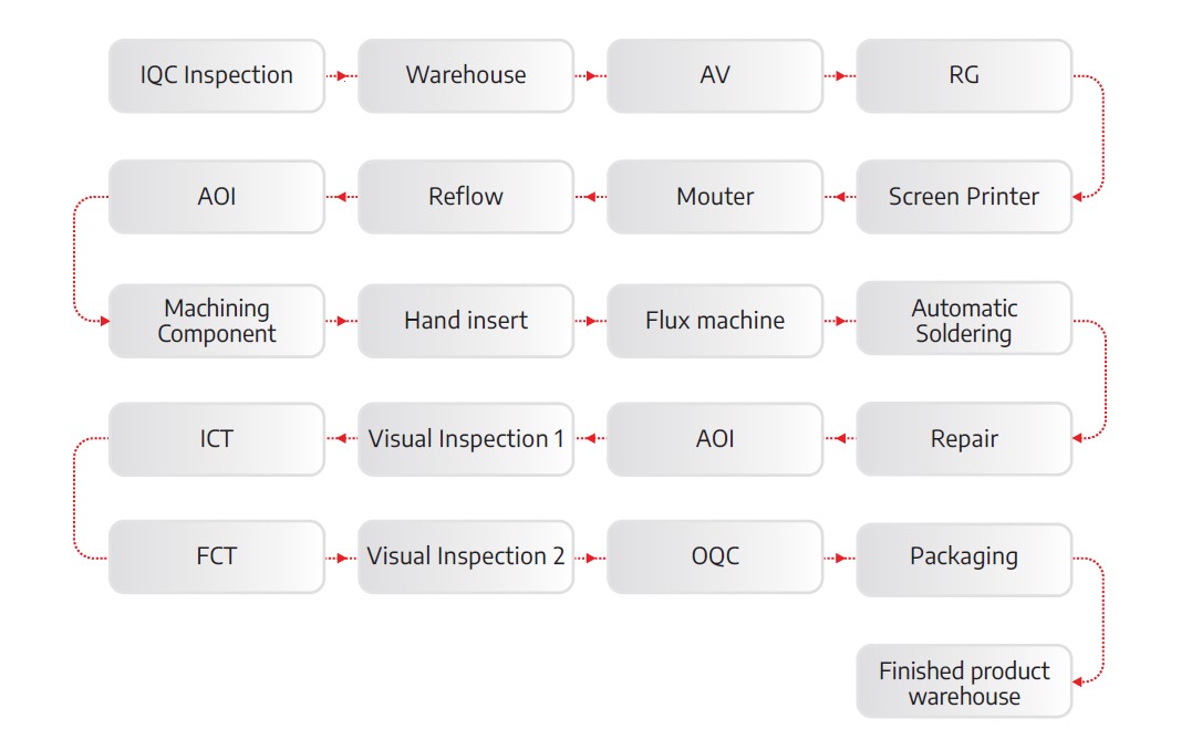
This process-oriented capability is important for Design for Manufacturing because DFM is not only a design review. It is a bridge between product engineering and production execution.
SHDC also has experience with PCBA applications in areas such as water purifiers, computer mouse products, petrol-related electronics, automotive-related PCBA, and charger products. For OEMs working on power electronics, chargers, control boards, consumer electronics, or industrial products, early DFM review can help reduce production risk before the project reaches volume production.
For brands looking for an end-to-end partner, SHDC can support full service EMS in Vietnam, including PCBA manufacturing, testing, assembly, and packaging. This is especially useful for OEMs that need one manufacturing partner to coordinate multiple production steps.
Design for Manufacturing for U.S. OEMs Working With Vietnam EMS Partners
U.S. OEMs often evaluate Vietnam-based EMS partners for supply chain diversification, cost structure, production capability, and long-term manufacturing flexibility. However, successful outsourcing requires more than sending files and asking for a quote.
To work effectively with a Vietnam EMS partner, OEMs should:
- Share complete engineering documentation
- Confirm quality expectations early
- Define inspection and testing requirements
- Discuss component sourcing risks
- Align on pilot production before mass production
- Respond quickly to DFM feedback
- Review packaging and shipping requirements
- Keep communication structured during NPI
For OEMs comparing manufacturing options, internal cost is not limited to unit price. Design changes, rework, inspection failures, test fixture delays, and poor communication can all increase total cost. A good DFM process helps reduce those hidden costs before they affect delivery.
OEMs can also review PCB assembly cost factors early so they understand how design complexity, component selection, testing requirements, and production volume influence the final quotation.
When Should You Request a DFM Review?
OEMs should request a Design for Manufacturing review before PCB fabrication, before ordering mass-production components, before pilot production, and before committing to mass production.
A DFM review is also useful when:
- Production yield is unstable
- The product has complex PCBA
- The design includes both SMT and DIP components
- The project requires functional testing
- The OEM is changing suppliers
- The product is moving from prototype to volume build
- The team needs to reduce cost without sacrificing quality
DFM should not be treated as a final check after everything is already locked. It should be part of the development process before major sourcing and production decisions are made.
Final Thoughts
Design for Manufacturing helps electronics OEMs turn a working design into a product that can be built consistently, tested reliably, and scaled efficiently. For PCBA and electronics products, DFM should cover PCB layout, component selection, SMT and DIP assembly, inspection, testing, documentation, final assembly, and packaging.
For U.S. OEMs working with overseas manufacturing partners, DFM is also a communication tool. It aligns engineering expectations with production reality and reduces the chance of costly surprises during pilot or mass production.
If you are preparing a PCBA or electronics product for manufacturing, SHDC can review your project requirements and support production from design review to SMT, DIP, testing, assembly, and final packaging.
FAQs About Design for Manufacturing
What does Design for Manufacturing mean in electronics?
Design for Manufacturing in electronics means reviewing PCB design, components, assembly method, testing, inspection, and documentation to ensure the product can be manufactured efficiently and consistently.
Why is DFM important for PCBA production?
DFM helps reduce soldering defects, component placement issues, poor test access, sourcing delays, rework, and redesign before mass production.
When should an OEM do a DFM review?
An OEM should request a DFM review before PCB fabrication, before pilot production, before ordering mass-production components, or before scaling from prototype to mass production.
What files are needed for a DFM review?
Common files include Gerber files, BOM, pick-and-place file, assembly drawing, PCB specifications, test requirements, firmware instructions, and packaging requirements.
Is DFM only useful for high-volume production?
No. DFM is useful for prototypes, pilot runs, and mass production because it helps detect risks early and improves the transition from design to production.
Can an EMS partner help with DFM?
Yes. An EMS partner can review the product from a manufacturing perspective and provide feedback on PCBA, SMT assembly, DIP assembly, testing, inspection, sourcing, and production flow.
