Tiếng Việt
 日本語
日本語
Medical devices are becoming smaller, lighter, more portable, and increasingly connected. That creates a problem for hardware engineers: the electronics still need to deliver stable electrical performance, but the available space is getting tighter and the mechanical environment is becoming more demanding. A rigid PCB works well when the electronics can sit on a flat, fixed surface. But what happens when the circuit needs to wrap around a curved enclosure, connect two modules at different angles, or move repeatedly with the product? This is where a flexible PCB for medical devices can become more than a space-saving alternative. A flex PCB can change the way electronics are physically integrated into a medical product, potentially reducing wiring, simplifying interconnections, and enabling compact designs that are difficult to achieve with rigid boards. The real question is not whether flex PCBs are “better” than rigid PCBs. It is why and when engineers should use them in medical devices—and what needs to be considered before taking a flex design into production.
Why Are Flex PCBs Used in Medical Devices?
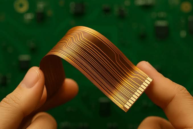
The main reason is simple: medical electronics increasingly need to fit around the product rather than force the product to fit around the electronics.
The U.S. FDA already recognizes wearable and sensor-based digital health technologies as an important category of medical devices, including wearables such as patches, bands, rings, and smartwatches used for continuous or spot monitoring.
For these products, PCB geometry can directly affect the mechanical design, user comfort, assembly complexity, and reliability of the final device.
Flex PCBs are particularly useful when a medical product requires:
- Limited internal space
- Curved or irregular mechanical structures
- Lightweight electronics
- Repeated movement or controlled bending
- Compact interconnection between multiple electronic modules
- Reduced reliance on cables and connectors
- Integration into wearable or portable form factors
Here are the key reasons engineers consider them.
1. Flex PCBs Solve Space Constraints in Compact Medical Devices
Space is often one of the first problems a medical product engineer encounters.
A rigid PCB has a fixed geometry. If the enclosure is curved or contains multiple mechanical sections, the board has to occupy a defined flat area somewhere inside the product. Cables and connectors may then be required to bridge the remaining gaps.
A flex PCB changes this constraint.
Instead of forcing every circuit section onto one flat board, engineers can design a flexible interconnect that follows the available mechanical space. The circuit can bend around corners, connect separated modules, or fit into narrow areas that would be difficult to reach with a rigid board.
This can be valuable in:
- Wearable patient monitoring devices
- Portable diagnostic equipment
- Compact medical sensors
- Handheld medical instruments
- Patient monitoring accessories
- Small electronic modules integrated into medical equipment
The advantage is not simply “smaller PCB size.” It is greater freedom in the overall mechanical-electrical architecture.
For OEMs developing wearable products, this is especially relevant because the electronics have to coexist with a product that may sit directly on the body. SHDC also covers the broader manufacturing considerations in its guide to a medical wearable device manufacturer.
2. Flex PCBs Can Reduce Wires and Connectors
Consider a conventional architecture:
PCB → cable → connector → cable → another PCB
Every additional cable and connector adds another mechanical and electrical interface.
A flexible circuit can sometimes replace part of that wiring architecture with a single integrated interconnect:
PCB → flexible circuit → another circuit or component
That does not mean every medical device should eliminate cables. It means engineers have another option when cable routing becomes complicated or space is limited.
Potential benefits include:
- Fewer separate wire assemblies
- Reduced connector count in some designs
- Less wiring congestion
- More compact internal architecture
- Fewer mechanical interfaces to manage
- Easier integration of electronics into constrained spaces
However, this should not be treated as an automatic reliability improvement. A poorly designed flex circuit can fail just as easily as a rigid PCB. The benefit comes from designing the flex circuit around the mechanical requirements of the product, rather than simply replacing a rigid board with a flexible one.
3. Flex PCBs Enable Wearable and Compact Medical Designs
Wearable medical electronics create a unique engineering challenge: the device has to function electrically while fitting into a product that moves with the user.
A rigid PCB can become a limitation when the product follows a curved surface or when the electronics need to be distributed across several locations.
A flex PCB can provide a continuous electrical connection while allowing the circuit to conform to the mechanical structure.
This makes flexible circuits attractive for applications such as:
- Wearable monitoring systems
- Health-monitoring patches
- Compact sensor modules
- Portable patient-monitoring equipment
- Small diagnostic devices
- Electronic medical accessories
The FDA’s current information on sensor-based digital health technologies includes wearable devices such as patches, bands, rings, and smartwatches, illustrating how healthcare electronics increasingly extend beyond conventional clinical equipment.
For engineers, the important point is that mechanical flexibility becomes part of the electrical design problem.
The PCB is no longer simply a flat platform for components. It becomes an interconnect that has to work within the physical movement and geometry of the product.
4. Flexibility Can Improve Mechanical Integration—but Only When the Bend Is Designed Correctly
This is where flex PCB design becomes much more technical.
A flexible circuit is not designed simply by making the PCB thinner. The bend area, copper structure, layer stack-up, materials, stiffeners, and component placement all influence how the circuit behaves under mechanical stress.
One of the most important parameters is the bend radius.
Engineers need to distinguish between:
- Static bending
- Dynamic bending
- Repeated flexing
- One-time installation bends
A circuit that is bent once during assembly has very different requirements from one that moves thousands of times during product operation.
Designers should therefore evaluate:
- Minimum bend radius
- Number of expected flex cycles
- Copper thickness
- Copper type and structure
- Layer count
- Coverlay construction
- Stiffener placement
- Connector transition areas
- Component placement near flex zones
The IPC-2223D flexible printed board design standard specifically addresses design requirements for flexible and rigid-flexible printed boards. IPC also identifies IPC-2223 as the sectional design standard covering flexible printed board applications.
So the right question is not:
“Can this PCB bend?”
It is:
“Can this PCB bend in the way the medical device requires, for the expected number of cycles, without compromising electrical or mechanical performance?”
That distinction matters.
5. Flex PCBs Can Help Make Medical Products Smaller and Lighter
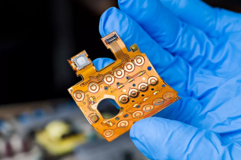
For portable and wearable medical products, every millimeter and gram can influence the final product.
A flex circuit may help reduce the space occupied by:
- Cable routing
- Separate interconnect assemblies
- Multiple connectors
- Rigid board-to-board connections
- Unused PCB area created by conventional layouts
This can create more freedom for mechanical engineers to reduce enclosure volume or redistribute components.
The result can be a product architecture that is:
Smaller → lighter → easier to integrate → potentially more comfortable to use
But these benefits should be evaluated at the system level, not only at PCB level.
A flex PCB that saves board space but requires complicated assembly or expensive materials may not actually improve the overall product.
That is why cost, manufacturability, reliability, and mechanical requirements need to be considered together.
6. Flex PCBs Can Simplify Electronics Architecture and Assembly
A flex PCB can also affect how the product is assembled.
Instead of treating the PCB, wires, and connectors as separate assemblies, a flexible circuit can integrate some of these functions into one interconnected structure.
This can potentially reduce:
- Wiring operations
- Connector installation
- Manual routing
- Mechanical fastening
- Assembly complexity
However, the manufacturing process becomes more sensitive to handling, component placement, stiffeners, flex-to-rigid transitions, and inspection requirements.
This is why a flex PCB should be reviewed from the beginning with Design for Manufacturing (DFM) in mind. SHDC’s DFM for electronics manufacturing resources cover how manufacturing constraints can be incorporated earlier in the product development process.
For a medical device, this matters even more because a design that is difficult to manufacture consistently can create problems during validation, quality inspection, and production scaling.
7. What Engineers Need to Consider When Designing a Flex PCB for Medical Devices
Choosing flexible circuitry is only the beginning. The design must account for both electrical and mechanical requirements.
Material selection
Polyimide is widely associated with flexible circuits because it offers the flexibility and thermal performance needed for many applications. However, the right material depends on the actual operating environment.
Engineers should evaluate:
- Operating temperature
- Moisture exposure
- Mechanical stress
- Cleaning and disinfection conditions
- Sterilization requirements, where applicable
- Signal frequency
- Required flexibility
- Long-term reliability
Material selection should not happen independently from manufacturing. A material that performs well electrically may introduce fabrication or assembly challenges.
Bend radius and flex zones
The flex zone should be deliberately defined.
Components are generally not placed in areas expected to undergo repeated bending. Stiffeners may be required around connectors or component areas to provide mechanical support.
The transition between rigid and flexible sections also deserves special attention because mechanical stress can concentrate at these points.
Signal integrity
Flexibility does not remove electrical requirements.
Medical electronics may process low-level signals from sensors or physiological measurements where noise can affect measurement accuracy.
For more demanding designs, engineers may need to consider:
- Controlled impedance
- Differential pair routing
- Ground reference
- Return current paths
- Crosstalk
- EMI/EMC performance
- Connector transitions
The electrical design therefore needs to be evaluated together with the mechanical structure.
Component placement
Component placement becomes especially important because not every part of the circuit can safely flex.
A practical architecture may separate the design into:
Rigid area → component placement → transition area → flexible interconnect → transition area → rigid area
This allows the flexible section to perform primarily as an interconnect while sensitive components remain on mechanically stable regions.
8. Flex PCB Manufacturing Challenges Medical OEMs Should Consider
Flex PCB design can solve one set of problems while introducing another.
Manufacturing teams need to consider:
Fabrication tolerances
Flexible substrates behave differently from rigid boards during fabrication and handling. Dimensional stability and process control therefore become important.
Component assembly
Components may be mounted on rigid sections, flexible sections, or rigid-flex structures depending on the design. The assembly process must account for the mechanical characteristics of the substrate.
Stiffeners and connector areas
Stiffeners may be required to reinforce areas around connectors or components. Their thickness and position can affect both mechanical integration and assembly.
Handling during assembly
Flex circuits can be more sensitive to handling than rigid boards. Production operators and automated equipment must accommodate the board’s physical characteristics.
Inspection and testing
A medical electronics manufacturer needs to verify both assembly quality and electrical functionality. This is where processes such as SPI, AOI, ICT, and functional testing become important.
SHDC’s PCB Assembly Quality Control resources cover inspection checkpoints from incoming materials through final inspection, while in-circuit testing provides a deeper look at electrical verification during PCB assembly.
Documentation
Production documentation becomes particularly important when a design contains multiple rigid and flexible regions, special materials, stiffeners, or unique assembly requirements.
A complete package may include Gerber files, BOM, pick-and-place data, assembly drawings, test procedures, and revision information. For a deeper reference, see SHDC’s guide to PCB assembly files.
9. When Should Medical OEMs Choose Flex PCB Over Rigid PCB?
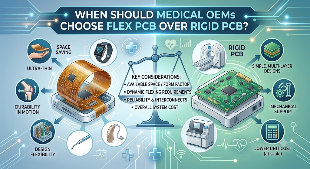
Flex PCB is not automatically the right solution for every medical product.
The better approach is to match the PCB architecture to the product requirements.
Flex PCB is worth considering when:
- Internal space is highly constrained
- The enclosure has curved or irregular geometry
- Electronics need to move or flex
- The product is wearable or highly portable
- Weight reduction is important
- Multiple electronic modules need compact interconnection
- Cable routing is becoming complicated
- Connector count is creating mechanical constraints
Rigid PCB may still be the better choice when:
- The board can remain completely flat
- There is sufficient internal space
- No repeated mechanical movement is expected
- Cable routing is simple
- Flexibility provides little practical benefit
- The additional cost or manufacturing complexity is not justified
In other words, the decision should not be Flex vs. Rigid based on trend.
It should be:
Which PCB architecture provides the best balance of mechanical integration, electrical performance, reliability, manufacturability, and total product cost?
For medical devices, this decision should be made during architecture and PCB design—not after the prototype has already been built.
10. Regulatory and Quality Considerations Still Apply
Flexibility does not reduce the regulatory expectations placed on a medical device.
For products entering the U.S. market, the FDA’s design-control framework requires manufacturers of applicable medical devices to establish and maintain procedures that ensure specified design requirements are met.
The FDA also updated its device quality-system framework in February 2026, when the Quality Management System Regulation (QMSR) became effective and incorporated ISO 13485:2016 by reference.
For medical electrical equipment, IEC 60601-1 addresses general requirements for basic safety and essential performance, while IEC 60601-1-2 addresses electromagnetic disturbances and related requirements and tests.
For flexible PCB design specifically, IPC-2223D provides design guidance for flexible and rigid-flexible printed boards.
This means flex PCB development needs to consider compliance from the beginning:
Product requirements → PCB architecture → material selection → layout → prototype → testing → verification → production
Compliance should not be treated as a final-stage checkbox.
For OEMs evaluating manufacturing partners, SHDC also provides resources covering ISO 13485 medical devices and traceability in electronics manufacturing.
11. From Flex PCB Design to Medical Device Production
A successful flexible PCB project does not end when the PCB passes electrical testing.
The design has to move reliably through the complete production chain:
Requirements → PCB design → DFM review → Prototype → Assembly → Inspection → Testing → Validation → Production
This is why early communication between the OEM’s engineering team and manufacturing partner can make a major difference.
Before production, the team should review:
- Flex and rigid section dimensions
- Bend radius requirements
- Component placement
- Stiffeners
- Connector design
- Material availability
- Assembly process
- Inspection strategy
- Testing requirements
- Production documentation
- Traceability requirements
For OEMs moving from prototype to commercial production, SHDC’s NPI electronics manufacturing approach is relevant because manufacturability and production readiness need to be considered before volume production begins.
The goal is not simply to produce a working flex PCB prototype.
The goal is to create a design that can be repeatedly manufactured, assembled, tested, and traced at the required production volume.
How SHDC Supports Medical Electronics Manufacturing
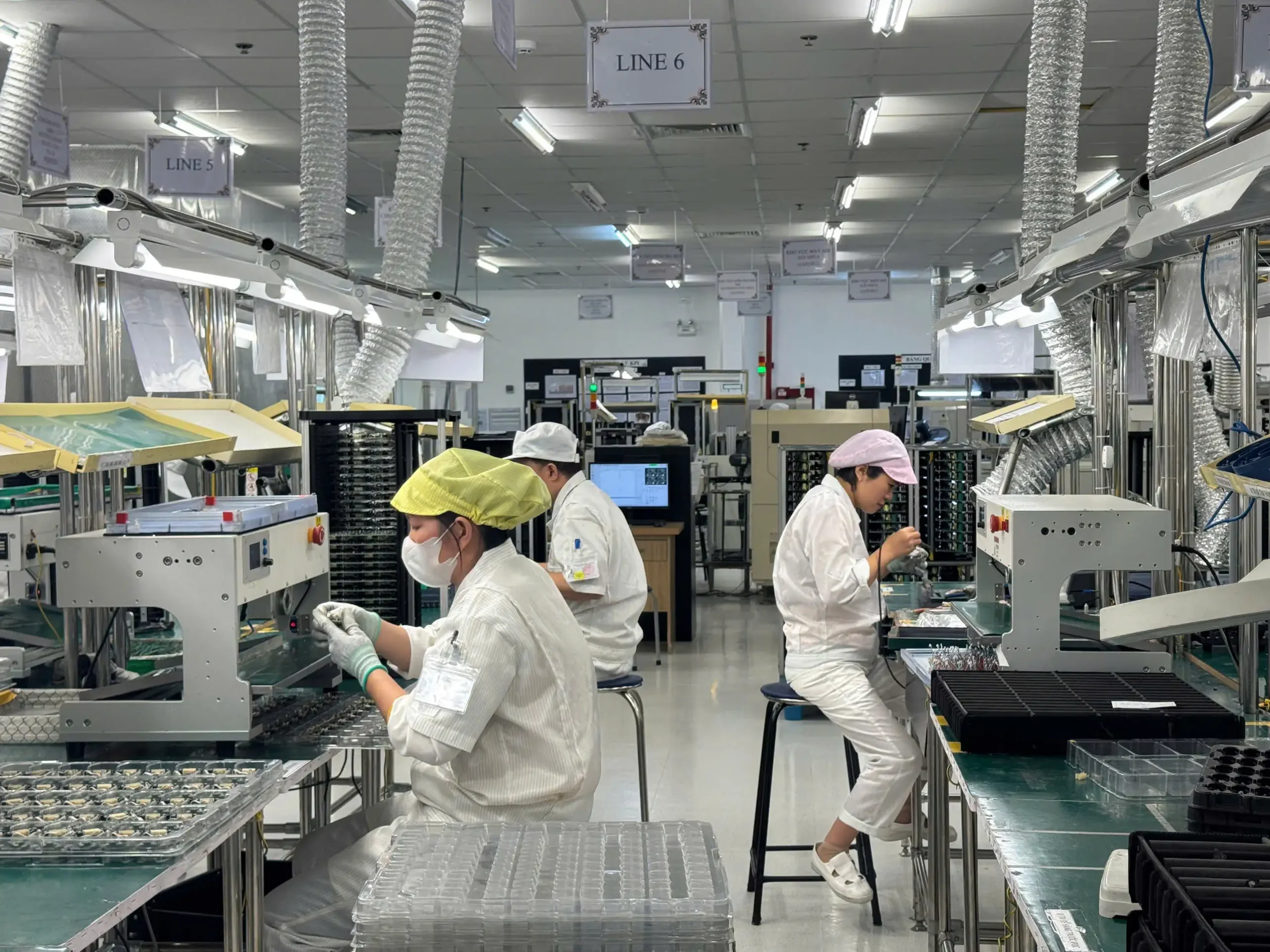
For medical electronics projects, manufacturing capability matters just as much as the PCB design itself.
SHDC Electronics provides EMS covering component soldering, assembly, testing, and final packaging, supported by a technical team and production systems focused on process improvement and reliability. Its current production profile includes four high-speed SMT lines, three DIP lines, and dedicated assembly, testing, and packaging operations.
The factory’s documented production capabilities include SMT and DIP processes, backend welding, testing, assembly and packaging, with equipment supporting SPI, AOI, ICT, functional testing, and other inspection and test operations.
For medical OEMs, this makes early manufacturing collaboration particularly valuable. A project can be evaluated not only from the perspective of PCB functionality but also from assembly, inspection, testing, documentation, and production readiness.
SHDC’s Medical Device PCB Assembly Vietnam resources provide a broader view of how PCB assembly can support medical electronics production, while its Medical Device EMS Provider content covers the wider manufacturing-partner perspective.
Conclusion: Flex PCB Is About More Than Flexibility
So, why are flex PCBs used in medical devices?
Because modern medical electronics increasingly need to work within physical constraints that rigid PCBs cannot always accommodate efficiently.
Flex PCBs can help engineers:
- Fit electronics into compact or curved spaces
- Reduce wiring and connector complexity
- Support wearable and portable products
- Improve mechanical integration
- Potentially reduce product size and weight
- Create more flexible electronics architectures
But flexibility alone does not guarantee a better medical device.
The real value comes when mechanical design, electrical performance, reliability, DFM, testing, and manufacturing are considered together.
For OEMs developing a flexible medical PCB, the most important question is therefore not simply “Can we use a flex PCB?”
It is:
“Can we design and manufacture the flex circuit in a way that remains reliable throughout the entire product lifecycle?”
That is the point where early engineering review and manufacturing collaboration become critical.
FAQs
What is a flexible PCB for medical devices?
A flexible PCB is a printed circuit board designed on a flexible substrate so that the circuit can bend or conform to a product’s mechanical structure. In medical electronics, it can be useful for compact, wearable, portable, or mechanically constrained products.
Why are flex PCBs used in wearable medical devices?
Wearable devices often have curved or space-constrained mechanical structures. Flex PCBs can allow electronic interconnections to follow those structures while potentially reducing cable and connector requirements.
Are flex PCBs more reliable than rigid PCBs?
Not automatically. Reliability depends on the design, materials, bend radius, flex cycles, component placement, connector transitions, assembly process, and operating environment. A flex PCB should be engineered for its actual mechanical and electrical conditions.
What materials are commonly used for medical flex PCBs?
Polyimide-based flexible materials are commonly considered for flexible circuits, but material selection should depend on temperature, moisture, mechanical stress, sterilization or cleaning requirements, electrical performance, and manufacturing constraints.
What should engineers consider before manufacturing a medical flex PCB?
Engineers should review bend radius, flex cycles, layer structure, copper construction, stiffeners, component placement, signal integrity, EMI/EMC, material availability, DFM, assembly, inspection, testing, documentation, and traceability before moving to production.