
 Tiếng Việt
 日本語
日本語
An automotive printed circuit board assembly can appear visually correct while still containing an electrical open, an incorrect component value or a functional problem that only becomes visible after power-up. Conversely, a board may complete a basic functional test even though it contains a placement or soldering condition that should have been identified earlier in production. For this reason, verifying an automotive PCBA in Vietnam should not depend on a single inspection method. A stronger test strategy combines three different layers:
- Automated optical inspection, or AOI, for visible assembly conditions.
- In-circuit testing, or ICT, for circuit-level electrical verification.
- Functional circuit testing, or FCT, for product-specific operation.
SHDC’s company profile lists a Yamaha YSi-V 3D AOI system, a Kyoritsu ICT F-2000 Plus and functional-testing equipment. Its documented production flow also places AOI, ICT and FCT before outgoing quality control and final packaging. The exact inspection and test route, however, must be defined for each product rather than assumed to be identical for every assembly.
This guide explains what each method can detect, where its limitations begin and what US automotive OEMs should provide when developing a PCBA verification plan with SHDC.
What Does Assembly Verification Mean for Automotive PCBA?
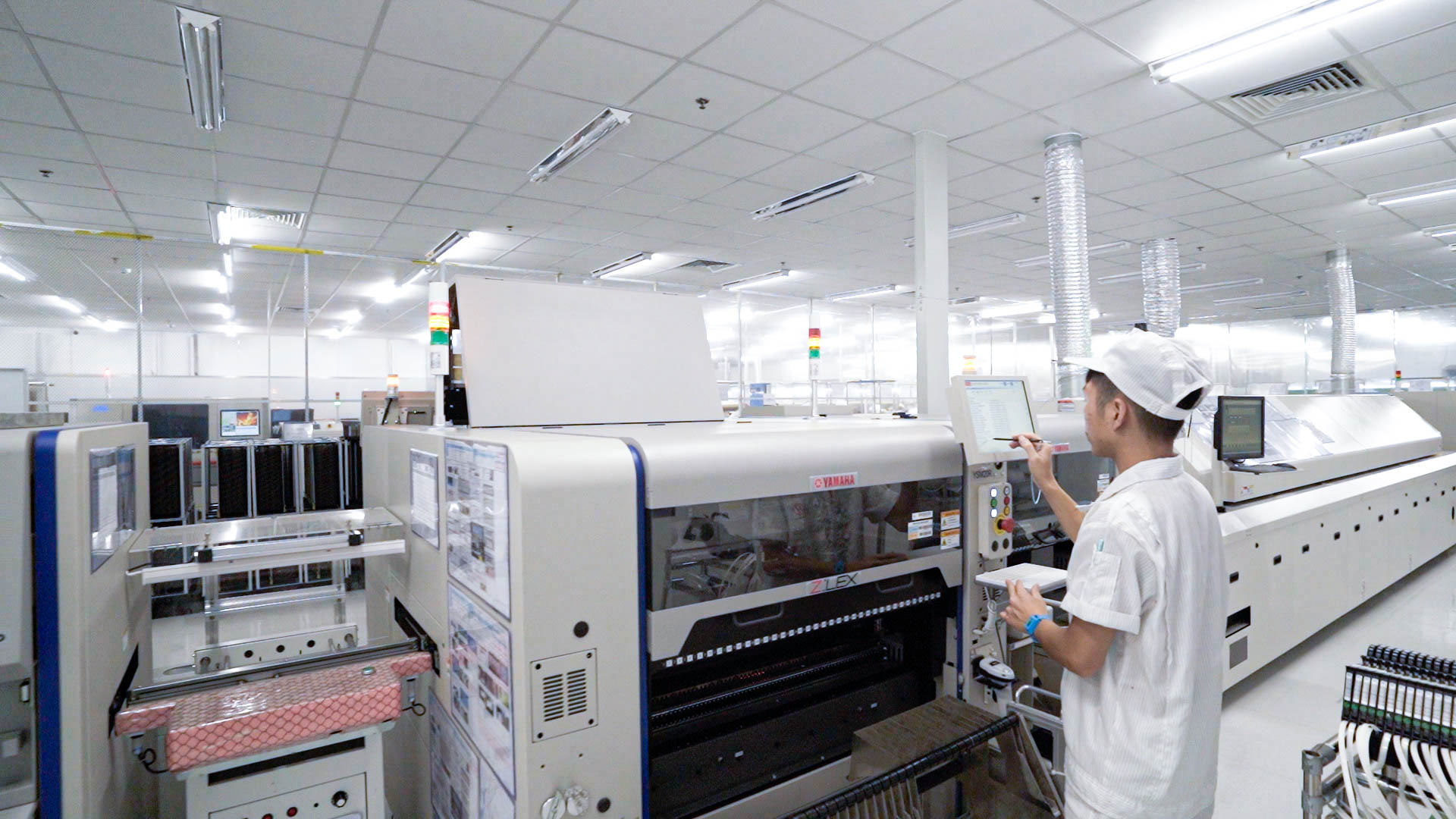
Assembly verification is the structured process of confirming that a PCBA has been built according to its design data and performs according to its approved functional requirements.
It includes three related but different activities.
Inspection evaluates physical assembly conditions such as component presence, orientation, position and visible solder-joint quality.
Electrical testing checks whether circuit connections and selected components behave as expected.
Functional testing determines whether the powered assembly carries out its intended operation under customer-defined conditions.
These activities should not be treated as interchangeable. IPC J-STD-001J covers materials, methods and process requirements for soldered assemblies, while IPC-A-610J provides post-assembly visual acceptance requirements. IPC released the current “J” revisions in 2024 and recommends using the documents together where applicable.
For a broader discussion of process controls surrounding these tests, see SHDC’s PCB assembly quality control plan.
Manufacturing Defects and Functional Failures Are Different
Common manufacturing defects include:
- Missing or misplaced components
- Incorrect polarity
- Solder bridges
- Open solder joints
- Insufficient solder
- Wrong component values
- Incomplete through-hole soldering
- Damaged or lifted leads
Functional failures may include:
- Incorrect power-up behavior
- Output voltage outside the specified range
- Communication failure
- Sensor inputs not responding correctly
- Relay or actuator outputs not operating
- Firmware not interacting correctly with the hardware
- Excessive current consumption
- Incorrect sleep or wake-up behavior
A visual system may detect the first group but cannot fully verify the second. An electrical test may identify an open net but may not confirm the complete operating sequence of the product. That is why effective automotive PCBA verification uses several test gates.
SHDC’s AOI, ICT and FCT Process at a Glance
| Verification stage | Primary question | Typical scope | Equipment shown in SHDC profile |
|---|---|---|---|
| AOI | Was the board assembled visibly as intended? | Component presence, orientation, position and visible solder conditions | Yamaha YSi-V 3D AOI |
| ICT | Is the circuit electrically assembled as designed? | Opens, shorts, connectivity and selected component values | Kyoritsu ICT F-2000 Plus |
| FCT | Does the assembly perform its intended functions? | Power, inputs, outputs, interfaces and customer-defined operations | Functional-testing equipment |
| Additional testing | Does the product meet special electrical or operating requirements? | High-voltage, aging or application-specific checks | Equipment shown in SHDC profile |
The SHDC process diagram shows AOI after reflow, followed by repair where required. ICT and FCT appear later in the production route, before OQC, packaging and finished-product storage. The equipment portfolio also includes high-voltage and aging-test equipment.
This confirms that SHDC has multiple inspection and testing resources. It does not mean every board automatically receives all listed tests. Test coverage, limits, frequency and data-retention requirements must be agreed during project review.
AOI for Automotive PCBA Assembly Verification
Automated optical inspection uses cameras, lighting and programmed inspection criteria to compare an assembled board with the expected component and soldering conditions.
AOI is normally positioned after SMT reflow because this allows the system to examine both component placement and visible solder-joint formation.
What AOI Can Inspect
Depending on the component package, image quality and inspection program, AOI may detect:
- Missing components
- Incorrect polarity or orientation
- Component rotation
- Placement offset
- Lifted leads
- Visible solder bridges
- Certain insufficient or excessive solder conditions
- Incorrect markings when visually distinguishable
- Components that are not seated correctly
The Yamaha YSi-V listed in SHDC’s profile combines two-dimensional inspection, three-dimensional inspection and four-direction oblique imaging in one platform. Angled imaging can provide additional views around component bodies and leaded packages that may be difficult to assess from a top-down image alone. (Yamaha Motor Global Site)
SHDC provides a more detailed explanation of automated optical inspection in PCB assembly.
AOI Programming Matters as Much as the Machine
Installing an AOI system does not automatically guarantee effective defect detection. A usable inspection program requires:
- A correct component library.
- Defined inspection regions.
- Polarity and marking references.
- Appropriate height and position limits.
- First-article verification.
- Review of false calls.
- Revision control when the BOM or PCB changes.
If thresholds are too broad, real defects may escape. If they are too narrow, the system may generate excessive false failures and slow production.
For automotive-related projects, the OEM should identify critical components, polarity-sensitive devices and solder joints that require particular attention.
What AOI Cannot Confirm
AOI cannot fully verify:
- Electrical continuity
- Resistance or capacitance values
- Firmware operation
- Communication protocols
- Product operating sequences
- Intermittent electrical faults
- Internal BGA solder connections without additional inspection
- Long-term product reliability
IPC-A-610J is a collection of visual acceptability requirements and does not provide criteria for X-ray or cross-section evaluation. An AOI pass should therefore not be interpreted as proof that the PCBA is electrically and functionally complete. (electronics.org)
AOI Defect Review and Repair
AOI results should enter a controlled review loop:
- The system flags a suspected condition.
- An operator or technician distinguishes a genuine defect from a false call.
- Confirmed defects are categorized.
- The board is transferred to controlled repair when allowed.
- The repaired area is reinspected and retested according to the work instruction.
- Defect data is reviewed for recurring process trends.
A defect Pareto can help identify whether failures originate primarily from solder paste printing, placement, reflow, component handling or inspection-program settings. Common defect mechanisms are discussed further in SHDC’s guide to common PCB assembly defects.
ICT for Circuit-Level Electrical Verification
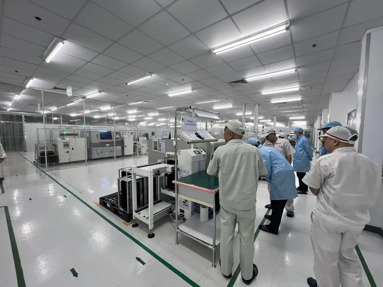
In-circuit testing uses electrical probes or a dedicated fixture to access points on the assembled PCB.
Depending on the board design and test program, ICT can evaluate:
- Open circuits
- Short circuits
- Continuity
- Resistor and capacitor values
- Diode orientation
- Basic semiconductor junctions
- Power and ground conditions
- Missing or incorrect components that create measurable electrical differences
Keysight describes ICT as a method for measuring electrical properties such as resistance, capacitance and voltage at specific PCB nodes. These measurements help identify opens, shorts and incorrect component values.
SHDC’s equipment profile lists the Kyoritsu ICT F-2000 Plus. The profile does not state a universal fault-coverage percentage, fixture configuration or test-node capacity, so these details should be confirmed for each project.
>>>Read more: Automotive PCBA Vietnam | Trusted Non-China Manufacturer for USA
Why ICT Supports Faster Fault Isolation
Suppose a board fails FCT because it does not power up.
FCT confirms that the product does not work, but it may not immediately show why. ICT can help isolate the underlying cause, such as:
- A short between the power and ground nets
- An open connection
- A reversed diode
- An incorrect resistor value
- A missing component
- An assembly fault at a measurable node
This diagnostic capability can reduce troubleshooting time and improve feedback to the assembly process.
ICT Depends on Design for Testability
ICT requires physical and electrical access. Test points should be incorporated before the PCB layout is released.
Relevant design considerations include:
- Test-point access to critical nets
- Sufficient pad size
- Probe spacing
- Access from one or both sides
- Stable ground references
- Board support to prevent flex
- Clearance around tall components
- Fixture alignment features
- Programming and power-injection points
Keysight notes that custom fixtures are normally required for each PCB layout and that good design for test can improve access while reducing fixture complexity.
OEMs should therefore complete a design for testability review before finalizing the PCB.
ICT Limitations
ICT does not normally verify the complete operating behavior of a product.
Its limitations may include:
- Reduced coverage when test access is limited
- Difficulty accessing dense packages or hidden nodes
- Fixture development cost
- Program-debug time
- Limited firmware verification
- Inability to simulate the complete operating environment
For low-volume projects, the value of a dedicated ICT fixture must be weighed against tooling cost and expected fault coverage.
FCT for Product-Specific Performance Verification
Functional circuit testing powers or stimulates the PCBA and observes whether it performs according to the approved product specification.
Unlike AOI and ICT, FCT is highly application-specific.
A functional test may verify:
- Input voltage and current
- Power-up sequence
- Output voltage or current
- Sensor inputs
- Relay or actuator outputs
- Analog and digital signals
- Communication interfaces
- Firmware and hardware interaction
- Fault-response behavior
- Product-specific operating modes
NI describes functional testing as verifying the operation of the combined system of components, commonly at one or more points in production and at the end of the manufacturing line.
For more detail on their different purposes, see SHDC’s comparison of ICT vs. functional testing.
The OEM Must Define the Functional Requirements
An automotive FCT program cannot be built from the PCB files alone.
The OEM may need to provide:
- Schematic
- Connector pinout
- Permitted input-voltage range
- Expected current consumption
- Input stimuli
- Expected outputs
- Timing limits
- Firmware
- Programming procedure
- Communication protocol
- Load conditions
- Fault-response criteria
- Pass/fail tolerances
Depending on the product, the test plan might include CAN, LIN, analog-sensor simulation, ignition states, load simulation or sleep and wake-up behavior. These are examples of possible automotive requirements; SHDC’s profile does not confirm that every protocol or interface is already supported.
Golden Samples and Test Limits
An approved reference assembly can help correlate a newly developed FCT fixture, but a golden sample should not replace an engineering specification.
The test program should include:
- Nominal values
- Upper and lower limits
- Measurement uncertainty
- Time-based conditions
- Fixture identification
- Instrument calibration
- Firmware revision
- Test-program revision
Limits that are too broad can permit escapes. Limits that are too narrow can create false failures and unnecessary retesting.
AOI vs. ICT vs. FCT
| Criteria | AOI | ICT | FCT |
|---|---|---|---|
| Main purpose | Visual assembly verification | Circuit-level electrical verification | Product-function verification |
| Typical production stage | After reflow or soldering | After assembly | Near the end of the process |
| Powered board required | Usually no | Depends on the test | Usually yes |
| Detects missing components | Yes, when visible and programmed | Sometimes electrically | Sometimes through functional failure |
| Detects visible solder bridges | Yes | Detects resulting short | May detect resulting malfunction |
| Measures component values | Generally no | Selected components | Usually only indirectly |
| Verifies firmware | No | Usually no | Yes, when included in test scope |
| Dedicated fixture | Not normally an ICT fixture | Usually required | Usually required |
| Main limitation | Cannot prove electrical function | Limited by test access | May not isolate root cause efficiently |
A practical way to understand the difference is:
AOI asks whether the board was assembled visibly as intended. ICT asks whether the circuit is electrically connected as expected. FCT asks whether the product works as intended.
How AOI, ICT and FCT Work Together
A layered verification strategy creates several defect-containment gates.
Gate 1: AOI Detects Visible Assembly Errors
Detecting a reversed diode or missing component immediately after reflow is generally more efficient than discovering it during a later electrical or functional test.
Gate 2: ICT Isolates Circuit-Level Faults
ICT can identify an open, short or incorrect component value before the board enters a longer functional sequence.
Gate 3: FCT Confirms Intended Operation
FCT checks product behaviors that cannot be confirmed through images or isolated component measurements.
Consider three examples:
Reversed diode: AOI may detect the polarity error, ICT may confirm the abnormal junction condition and FCT may show that the board cannot operate.
Hidden open connection: AOI may pass the board, ICT may identify the open net and FCT may only report a broader functional failure.
Incorrect firmware: AOI and ICT may both pass, while FCT detects incorrect communication or operating behavior.
No combination delivers automatic 100% fault coverage. The remaining risk depends on PCB design, component accessibility, inspection algorithms, fixture design, test limits and process maintenance. Keysight recommends combining ICT with complementary visual and functional methods to address coverage gaps.
>>>Read more: Vietnam Automotive Electronics Manufacturing: The Complete Guide for Global OEMs and Tier-1 Suppliers (2026)
From Pilot Build to Automotive Production Approval
AOI, ICT and FCT should be developed and validated during the pilot-build stage rather than first introduced at mass production.
Activities may include:
- Debugging AOI inspection regions
- Reviewing false calls
- Validating ICT probe contact
- Correlating fixture measurements
- Confirming FCT sequences
- Establishing pass/fail limits
- Measuring test-cycle time
- Reviewing first-pass yield
- Investigating no-fault-found results
- Confirming repaired-board retest requirements
SHDC’s article on production validation testing provides additional context for confirming manufacturing readiness before volume production.
Automotive Documentation Context
When required by the customer, inspection and test records may support:
- Control plans
- Pilot-build reports
- Failure Pareto analysis
- Fixture-validation records
- Calibration records
- First-pass yield reporting
- Rework documentation
- Production-part approval evidence
AIAG’s current quality-core-tool resources include APQP 3rd Edition and the standalone Control Plan 1st Edition. The updated guidance includes topics such as sourcing, change management, traceability, risk mitigation and gated program management.
Automotive requirements must also be reviewed against the actual customer. The IATF maintains separate customer-specific requirements for individual OEMs, and these documents can change over time.
SHDC’s Supporting Assembly and Test Infrastructure
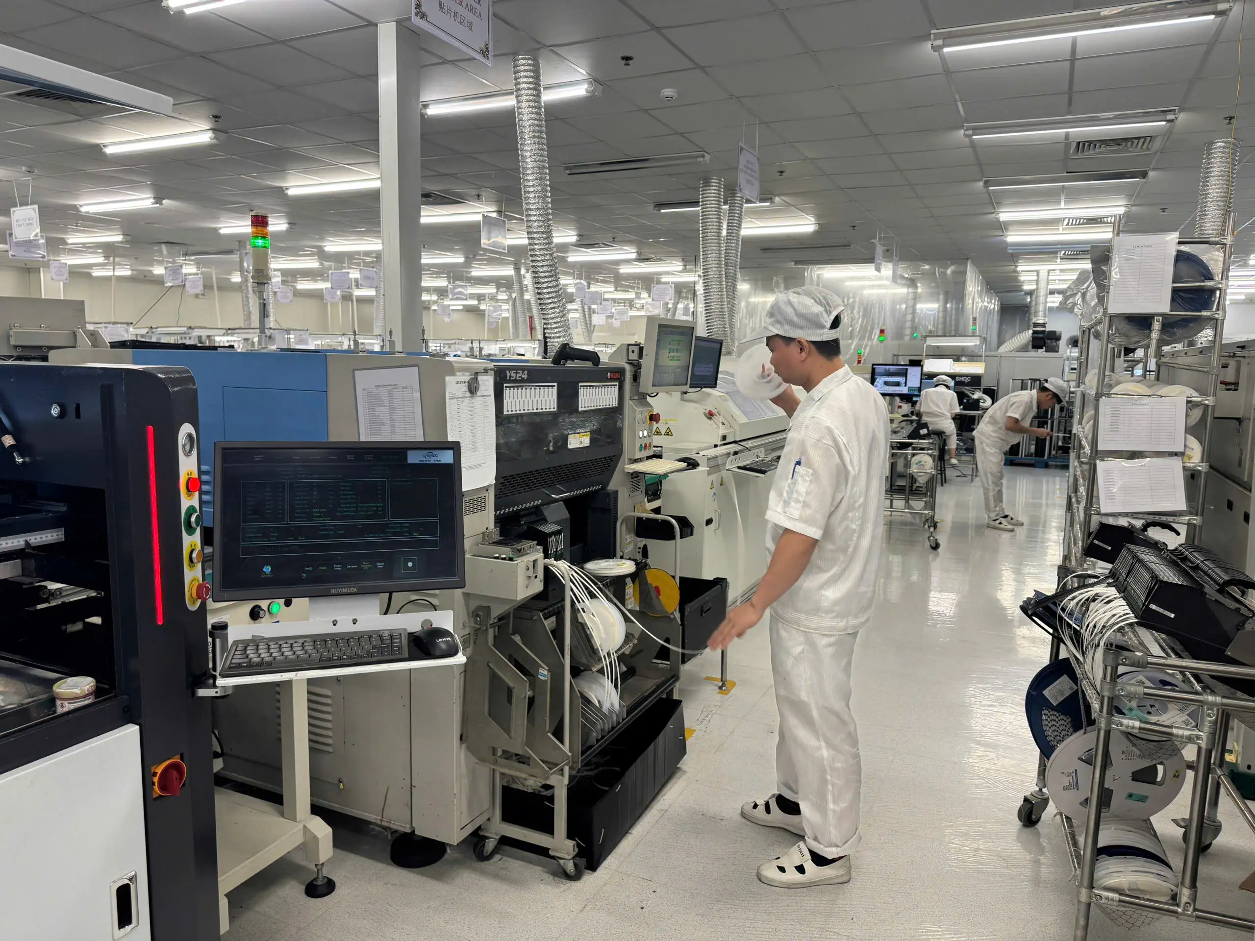
SHDC states that its EMS scope extends from component soldering, assembly and testing through final packaging.
Its current company profile lists:
- Four high-speed SMT lines
- Three DIP lines
- One assembly line
- One test line
- One packaging line
- Yamaha YSi-V 3D AOI
- Kyoritsu ICT F-2000 Plus
- Functional-testing equipment
- High-voltage testing
- Aging testing
- OQC and final packaging
The profile also shows QC, production and engineering functions within the organization and a production-management architecture connecting printing, SPI, placement, AOI, data and repair stations.
These facts support discussion of SHDC’s assembly and testing infrastructure. They do not by themselves establish:
- IATF 16949 certification
- A universal automotive control plan
- 100% AOI, ICT and FCT on every PCBA
- Specific CAN or LIN test capability
- X-ray inspection capability
- Guaranteed fault-coverage percentages
- Full serial-level test-data traceability
Those requirements should be confirmed during technical and commercial review.
For a wider overview of automotive manufacturing considerations, see automotive PCB assembly in Vietnam for US OEMs.
What US OEMs Should Provide to SHDC

A complete automotive PCBA test package should contain:
Manufacturing data
- Gerber or ODB++ files
- BOM with manufacturer part numbers
- Pick-and-place data
- Assembly drawings
- Schematic
- PCB specifications
- Approved alternates
AOI requirements
- Polarity references
- Critical-component list
- Marking variations
- Visual acceptance criteria
- Special solder-joint requirements
ICT requirements
- Netlist
- Test-point data
- Expected component values
- Coverage targets
- Retest rules
- Fixture-ownership requirements
FCT requirements
- Connector pinout
- Power conditions
- Input stimuli
- Expected outputs
- Timing requirements
- Firmware and programming files
- Communication requirements
- Pass/fail limits
Quality requirements
- Product and test-program revision control
- Data-retention period
- Serial or lot traceability
- Calibration requirements
- Rework and retest procedure
- Customer-specific submission requirements
- Change-notification rules
SHDC’s PCBA manufacturer Vietnam RFQ checklist provides a broader list of information needed for technical review and quotation.
>>>Read more: SHDC SMT Vietnam: A Leading SMT Assembly Partner for Global OEM Electronics
Automotive PCBA Verification Checklist
Before releasing a project into production, confirm that:
- Critical defect types have been identified.
- AOI coverage and limitations are documented.
- ICT test points are available.
- Fixture ownership and maintenance are agreed.
- FCT inputs, outputs and timing limits are defined.
- Firmware revisions are controlled.
- Golden samples are approved and identified.
- Pass/fail limits come from engineering specifications.
- Retest and repair rules are documented.
- Repaired boards receive appropriate reinspection.
- Test equipment calibration is current.
- Test-program revisions are controlled.
- Required test records can be linked to the production lot or serial number.
- Pilot-build results are approved before mass production.
- Customer-specific automotive requirements have been reviewed.
Conclusion
Effective verification of an automotive PCBA in Vietnam requires more than checking whether the board looks correct or powers on.
AOI, ICT and FCT address different risks:
- AOI identifies visible placement and soldering conditions.
- ICT checks circuit connectivity and selected component-level characteristics.
- FCT confirms customer-defined operating behavior.
The value of these methods depends not only on the equipment but also on design for testability, program development, fixture control, pass/fail limits, calibration and test-data management.
SHDC’s company profile confirms the presence of AOI, ICT and functional-testing equipment within its broader PCBA production process. For a specific automotive program, the OEM and SHDC should agree on the inspection route, test coverage, documentation and approval requirements before the pilot build begins.
Frequently Asked Questions About Automotive PCBA Testing
Is AOI enough for automotive PCBA verification?
No. AOI evaluates visible assembly conditions but does not fully verify electrical integrity, firmware or product function. ICT and FCT may be required depending on the product risk and customer specification.
What is the difference between AOI, ICT and FCT?
AOI checks visible assembly conditions. ICT measures circuit connections and selected components. FCT powers or stimulates the board to confirm that it performs its intended functions.
Does every automotive PCBA need all three tests?
Not automatically. The required test route depends on PCB design, production volume, failure risks, test access and customer-specific requirements.
Can AOI inspect BGA solder joints?
Conventional AOI cannot fully examine hidden solder joints under a BGA. X-ray or other methods may be required when the product risk justifies them.
What defects can ICT detect?
Depending on the fixture and program, ICT can detect opens, shorts, connectivity problems, selected incorrect component values and certain polarity or junction faults.
What does FCT test?
FCT may check power-up behavior, current consumption, inputs, outputs, communication, firmware interaction and other product-specific operating modes.
Why is design for testability important?
DFT creates the physical and electrical access required by ICT and FCT. It can improve fault coverage, simplify fixtures and reduce troubleshooting time.
Can SHDC provide automotive PCBA testing?
SHDC’s profile shows 3D AOI, Kyoritsu ICT F-2000 Plus and functional-testing equipment. The exact automotive test scope, coverage and reporting requirements must be confirmed for each project.
>>>Read more: Automotive Electronics Suppliers Southeast Asia — Vietnam, Thailand & Malaysia Compared (2026)
