Tiếng Việt
 日本語
日本語
For a US OEM, PCB Assembly Quality Control is not simply a final visual check performed before shipment. It is a controlled system that begins before production and continues through material inspection, solder-paste printing, component placement, reflow, inspection, electrical testing, traceability, nonconformance management, and outgoing quality control. Without a documented quality plan, a manufacturer may use the wrong component revision, overlook soldering defects, apply unclear test limits, or lose the ability to trace a failed assembly back to its material lot and production history.
A strong PCB assembly quality control plan connects product requirements with measurable checkpoints, acceptance criteria, inspection records, and reaction plans. This guide explains what US sourcing managers, supplier quality engineers, and hardware teams should verify before approving a PCBA supplier.
What Is PCB Assembly Quality Control?

PCB assembly quality control is the set of operational checks used to confirm that materials, manufacturing processes, workmanship, test results, and finished assemblies meet approved requirements.
It includes far more than AOI or functional testing. Effective control covers:
- Incoming PCB and component inspection
- Production-document verification
- Solder-paste and stencil controls
- Pick-and-place verification
- Reflow-profile monitoring
- AOI, X-ray, and visual inspection
- Through-hole assembly control
- ICT and functional testing
- Firmware and labeling verification
- Traceability
- Rework and nonconformance management
- Final lot release
A broader explanation of how quality assurance and inspection work across an EMS organization is available in this guide to QA/QI in EMS.
Quality assurance vs. quality control
Quality assurance and quality control support the same objective, but they perform different functions.
Quality assurance focuses on building a repeatable system. It includes procedures, training, document control, equipment maintenance, supplier management, internal audits, and preventive actions.
Quality control focuses on verifying a specific material, process, or product. Examples include measuring solder-paste volume, inspecting component polarity, reviewing an AOI result, or testing an assembled board.
Inspection and testing are therefore parts of quality control, but they do not represent the entire quality system.
Process control vs. final inspection
Final inspection cannot compensate for an unstable production process.
A board may look acceptable externally but still contain:
- A wrong component value
- An unapproved substitute
- An incorrect firmware version
- A hidden BGA soldering defect
- An intermittent electrical fault
- A material-lot traceability gap
- An undocumented rework
PCB assembly quality control must manage the material, machine, method, operator, environment, measurement system, and production data throughout manufacturing.
Defect detection vs. defect prevention
AOI, X-ray, ICT, and FCT help detect defects. Process control helps prevent those defects from occurring.
For example:
- AOI can identify a missing component.
- Feeder verification can prevent the wrong component from being loaded.
- SPI can detect insufficient solder paste.
- Stencil and printer controls can reduce the chance of insufficient deposits.
- Functional testing can identify an incorrect output.
- Controlled firmware and BOM revisions can prevent the wrong configuration from entering production.
The objective is not only to separate good boards from defective boards. It is to maintain a stable process that consistently produces acceptable assemblies.
Define PCB Assembly Quality Requirements Before Production
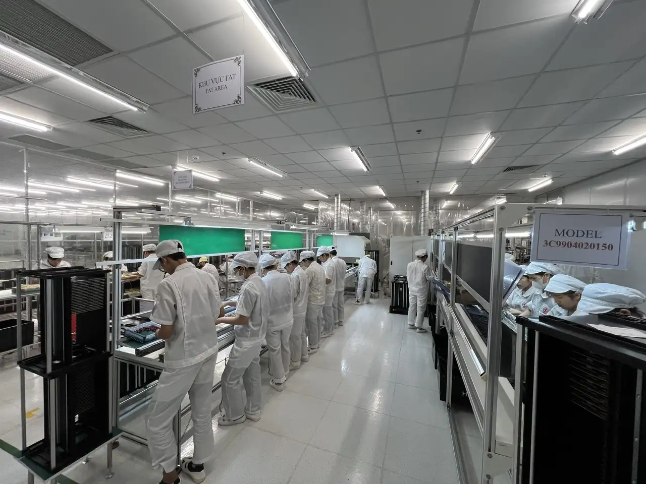
Many quality disputes begin because the OEM and manufacturer did not establish clear acceptance criteria before the first build.
A purchase order that only says “boards must be high quality” does not define:
- The applicable workmanship standard
- Product class
- Inspection coverage
- Test requirements
- Acceptable cosmetic conditions
- Substitution rules
- Rework authorization
- Traceability level
- Documentation requirements
These items should be agreed upon during quotation, engineering review, or production-readiness approval.
Agree on applicable acceptance criteria
IPC-A-610J provides visual acceptance criteria for electronic assemblies, while IPC J-STD-001J covers materials, methods, and acceptance requirements for soldered electrical and electronic assemblies. The OEM and supplier should identify the required standard, revision, product class, and customer-specific exceptions in the drawing, purchase order, contract, or quality agreement.
SHDC also maintains dedicated articles explaining IPC-A-610 acceptance criteria and the differences between IPC J-STD-001 and IPC-A-610.
The OEM should avoid assuming that a supplier automatically applies a specific class to every project. The required class and acceptance conditions should be stated explicitly.
Establish a quality agreement
A PCBA quality agreement may define:
- Approved BOM and Approved Vendor List
- Component-substitution approval
- Applicable drawings and revisions
- Inspection and test coverage
- Sampling or 100% inspection requirements
- First article approval
- Rework and repair authorization
- Deviation and concession procedures
- Change-notification requirements
- Traceability expectations
- NCR and CAPA response
- Record-retention period
- Shipment-release documentation
Commercial terms can remain in the supply agreement, while the quality agreement defines how product conformity will be controlled.
Identify critical-to-quality characteristics
Critical-to-quality characteristics depend on the product. They may include:
- Component polarity
- Safety-related component identity
- Solder-joint acceptability
- Connector alignment
- High-voltage clearance
- Firmware version
- Thermal-interface installation
- Product dimensions
- Output voltage or current
- Communication-interface performance
- Label and serial-number accuracy
These characteristics should receive clearly defined control methods and escalation rules.
What Should a PCB Assembly Quality Control Plan Include?
A quality control plan converts product requirements into operational checkpoints.
| Control-plan field | What it should define |
|---|---|
| Process step | Where the control occurs |
| Quality characteristic | What is being verified |
| Specification | Required value or acceptance condition |
| Control method | Inspection, measurement, or test method |
| Frequency | First piece, sampling, per lot, or 100% |
| Equipment | Tool, gauge, machine, or fixture |
| Record | Evidence retained after inspection |
| Reaction plan | Action when a result is outside limits |
| Owner | Responsible department or role |
A control plan should be product-specific. A generic factory process flow may describe the manufacturing stages, but it does not identify the exact tolerances, inspection frequency, test limits, or reaction plan for an individual product.
Control frequency and sampling
Manufacturers may use several control frequencies:
- First-piece inspection
- Per-lot inspection
- Periodic process checks
- Statistical sampling
- 100% automated inspection
- 100% electrical or functional testing
There is no single inspection frequency appropriate for every PCBA. The decision should consider product risk, production volume, process capability, customer requirements, and the consequence of failure.
Safety-related or function-critical features may require more extensive control than general cosmetic characteristics.
Define a reaction plan
Every major checkpoint should include a reaction plan.
The plan should answer:
- When must production stop?
- How many boards must be contained?
- Must the previous accepted boards be rechecked?
- Who can authorize production restart?
- Is customer approval required?
- Which records must be created?
- Does the defect trigger root-cause analysis or CAPA?
Without a reaction plan, inspection may identify a problem without controlling the potentially affected lot.
>>>Read more: PCB Assembly Files: Gerber, BOM, Pick-and-Place and Assembly Drawing Requirements
Pre-Production Quality Planning
PCB assembly quality control begins before materials reach the line.
Technical-data and revision review
Engineering should verify that all approved production documents describe the same configuration:
- Gerber, ODB++, or other fabrication data
- BOM
- Pick-and-place file
- Assembly drawing
- Schematic
- Test specification
- Firmware
- Mechanical documents
- Product revision
Document mismatches can result in correct execution of the wrong design. Revision control is therefore a quality-control requirement, not merely an administrative task.
Design changes should be released through a controlled Engineering Change Order process, rather than by replacing individual files through separate email messages.
DFM, DFA, and DFT review
Pre-production review should identify issues that may affect assembly, inspection, and testing, such as:
- Pad and component compatibility
- Polarity visibility
- Component spacing
- Panel requirements
- Test-point accessibility
- Hidden solder joints
- Manual assembly operations
- Inspection limitations
- Thermal constraints
- Mechanical interference
A structured DFM checklist for PCBA manufacturing helps engineering teams identify manufacturing risks before pilot production.
Process risk assessment
For higher-risk products, the supplier and OEM may review:
- Process sequence
- Potential failure modes
- Critical process parameters
- Special characteristics
- Existing preventive controls
- Detection controls
- Escalation rules
The objective is to place controls where failures can be prevented or detected most effectively.
First article and pilot-build approval
The quality plan should define:
- First article quantity
- Required measurements
- Inspection report format
- Test evidence
- Approved samples
- Customer-approval responsibility
- Conditions for beginning volume production
A supplier should not assume that passing automated inspection alone constitutes customer approval of the first article.
Incoming Quality Control for PCBs and Components

Incoming Quality Control, or IQC, confirms that materials match the approved requirements before they enter production.
Bare PCB incoming inspection
Bare PCB checks may include:
- Part number and revision
- Supplier and lot
- Board dimensions
- Thickness
- Surface finish
- Solder-mask condition
- Silkscreen
- Warpage
- Hole and slot dimensions
- Quantity
- Packaging condition
- Supplier documentation
The required inspection depth should reflect the board design, supplier history, and product risk.
Electronic-component verification
Incoming component controls may verify:
- Manufacturer part number
- Approved manufacturer
- Quantity
- Lot and date code
- Package type
- Marking
- Physical condition
- Moisture-barrier packaging
- Approved substitution status
- Customer-supplied material status
A substitute component should not be released merely because it appears electrically similar. Approval should follow the BOM, AVL, engineering-change, or deviation process established with the OEM.
Moisture-sensitive component control
Moisture-sensitive components may require controls for:
- Packaging condition
- Moisture-barrier bag integrity
- Humidity indicator
- MSL identification
- Floor-life tracking
- Exposure records
- Storage conditions
- Baking records where applicable
- FIFO or FEFO handling
Exact exposure and baking requirements depend on the component, packaging, and applicable manufacturer or industry documentation.
ESD controls
Sensitive electronic components and assemblies should be handled under a documented ESD control program.
US OEMs may verify:
- Protected work areas
- Personnel grounding
- Wrist-strap and footwear checks
- ESD-safe work surfaces
- Grounding verification
- Packaging and storage
- Monitoring records
- Training
- Periodic compliance verification
ANSI/ESD S20.20 provides a framework for establishing and maintaining an ESD control program for organizations handling susceptible electronic parts, assemblies, and equipment.
>>>Read more: EMS in Vietnam: How OEMs Should Choose the Right Manufacturing Partner
Solder Paste Printing and SPI Control
Solder-paste printing is a critical SMT process because paste volume, position, and consistency directly influence solder-joint formation.
Solder-paste handling
A controlled process may document:
- Product identification
- Lot number
- Storage condition
- Expiration
- Thawing time
- Mixing
- Time on the line
- Paste additions
- Disposal conditions
Records should prevent expired, unidentified, or improperly handled material from entering production.
Stencil and printer controls
Important controls may include:
- Stencil part number and revision
- Aperture condition
- Cleanliness
- Board support
- Alignment
- Squeegee pressure
- Squeegee speed
- Separation settings
- Cleaning frequency
- Print verification
The reaction plan should define what happens when print quality begins to drift.
Solder Paste Inspection
SPI systems can evaluate characteristics such as:
- Paste volume
- Height
- Area
- Position offset
- Insufficient deposits
- Excess deposits
- Bridging risk
The quality plan should establish warning limits, rejection limits, verification requirements, and process-adjustment rules. Collecting SPI data without acting on process trends provides limited preventive value.
Pick-and-Place Process Quality Control
Pick-and-place controls help prevent wrong components, placement errors, polarity mistakes, and product-variant mix-ups.
Line clearance and program verification
Before beginning a new production run, the team should confirm:
- Previous-model materials have been removed
- The correct product and revision are selected
- The approved machine program is loaded
- The correct BOM and variant are active
- Feeders match the setup list
- Work instructions are available
- Inspection and test programs match the build
Line clearance is especially important in high-mix manufacturing environments.
Feeder and component verification
Verification may use:
- Part-number checks
- Barcode scanning
- Feeder-position confirmation
- Package verification
- Polarity checks
- Lot recording
- Operator and system authorization
The goal is to prevent an incorrect reel from being installed at the wrong feeder position.
First-piece inspection
A first-piece or first-article check may verify:
- Reference designator
- Part identity
- Package
- Placement
- Rotation
- Polarity
- Product variant
- DNP status
- Missing or extra parts
Approval should be recorded before unrestricted production begins.
Placement-process monitoring
Manufacturers may monitor:
- Feeder alarms
- Mis-picks
- Component loss
- Vision errors
- Nozzle condition
- Placement offsets
- Manual interventions
- Program changes
Repeated alarms should trigger investigation rather than repeated operator overrides.
Reflow Soldering Quality Control
Reflow control helps ensure that solder joints form under an appropriate thermal process.
Reflow-profile approval
The profile should consider:
- Solder-paste requirements
- PCB thermal mass
- Component temperature limits
- Board density
- Panel configuration
- Product-specific requirements
A profile should not be copied automatically from another board without technical verification.
Parameters to monitor
Depending on the process, monitored parameters may include:
- Ramp rate
- Soak region
- Time above liquidus
- Peak temperature
- Cooling rate
- Conveyor speed
- Oven-zone settings
- Nitrogen conditions where applicable
The approved limits should reflect the materials and design used in the specific assembly.
Profile verification and records
The control plan should define when the profile must be reverified, including after:
- Equipment maintenance
- Product revision
- Panel change
- Solder-paste change
- Significant component change
- Process alarm
- Prolonged production interruption
Approved profiles and verification results should remain linked to the relevant product or process configuration.
AOI, X-Ray, and Visual Inspection Checkpoints
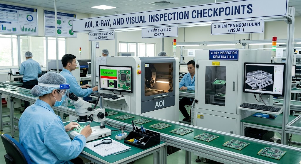
No single inspection method detects every type of PCB assembly defect.
Automated Optical Inspection
AOI can help identify:
- Missing components
- Incorrect components
- Polarity errors
- Placement shifts
- Solder bridges
- Some visible solder-joint abnormalities
A detailed explanation is available in SHDC’s guide to Automated Optical Inspection in PCB assembly.
AOI results still require controlled verification. An automated call may be a true defect or a false call, and the verification criteria should be documented.
X-ray inspection
X-ray may be appropriate for hidden or partially hidden solder joints, including:
- BGA
- QFN
- Bottom-terminated components
- Other packages where optical inspection cannot see the complete connection
The inspection level may be first article, sampling, process-validation, or 100%, depending on the product and risk plan. IPC J-STD-001J includes updated guidance concerning X-ray inspection of solder conditions that are not visible through other means.
Visual inspection
Visual inspection remains useful for conditions such as:
- Connector alignment
- Mechanical components
- Hand-soldered areas
- Cable routing
- Labels
- Cleanliness
- Physical damage
- Hardware installation
- Conditions not covered effectively by AOI
Inspectors should use defined acceptance criteria rather than subjective descriptions such as “looks good.”
False-call and program control
An AOI program with excessive false calls can create inspection fatigue and unnecessary handling. Program changes should therefore be:
- Authorized
- Revision-controlled
- Verified
- Recorded
- Linked to the applicable product
Operators should not loosen inspection limits simply to increase line throughput.
Through-Hole and Manual Assembly Quality Control
Through-hole and manual processes require the same level of control as automated SMT operations.
Component insertion
Controls may verify:
- Part identity
- Polarity
- Seating
- Lead forming
- Connector orientation
- Component height
- Mechanical alignment
Wave and selective soldering
Process controls may cover:
- Flux application
- Preheat
- Conveyor settings
- Solder conditions
- Fixture identification
- Solder fill
- Bridging
- Icicles
- Insufficient solder
- Cleanliness
The manufacturer should establish product-specific settings and inspection criteria.
Manual soldering and mechanical assembly
Manual operations may require:
- Qualified operators
- Approved tools
- Controlled work instructions
- Tip-condition checks
- Torque requirements
- Fastener verification
- Cable-routing checks
- Heat-sink installation
- Adhesive or thermal-material controls
Manual work should be traceable and inspectable, rather than treated as an informal correction step.
ICT and Functional Testing Within the Quality Plan
Testing verifies electrical and functional characteristics that optical inspection cannot confirm.
What ICT verifies
In-Circuit Testing may detect:
- Opens
- Shorts
- Connectivity problems
- Component presence
- Some incorrect component values
- Certain assembly defects accessible through test points
What functional testing verifies
Functional testing may evaluate:
- Inputs and outputs
- Interfaces
- Firmware behavior
- Communication
- Power performance
- Product operating functions
- Customer-defined pass/fail limits
The differences and use cases are explained further in ICT vs. Functional Testing.
Test program and fixture control
A test result is only meaningful when the test system itself is controlled.
The quality plan should address:
- Test-program revision
- Fixture identification
- Calibration
- Preventive maintenance
- Golden samples
- Limit settings
- User access
- Retest rules
- Data storage
- Failed-unit handling
A high test yield does not necessarily prove high production quality if the test coverage or limits are inadequate. OEMs should review how test requirements are defined in the broader PCBA testing process.
Final Quality Control and Lot Release
Outgoing Quality Control, or OQC, confirms that the approved product and shipment requirements have been met.
Final inspection checklist
Final checks may include:
- Workmanship
- Cleanliness
- Physical condition
- Product revision
- Firmware version
- Labels
- Serial numbers
- Dimensions
- Accessories
- Packaging
- Quantity
- Shipment identification
The checklist should match the product configuration and customer agreement.
Shipment-release documentation
Depending on the contract, a release package may include:
- Inspection report
- Test summary
- Certificate of Conformity
- Traceability record
- First article approval
- Approved deviation
- Packaging record
Not every project requires every document, but the required deliverables should be agreed upon before shipment.
Sampling vs. 100% inspection
A 100% final inspection does not eliminate the need for process control. Inspecting every unit cannot reliably identify every hidden, intermittent, or untested condition.
Sampling may be appropriate for some characteristics, while function-critical or safety-related requirements may need more extensive verification. The selected method should be documented in the quality plan.
Traceability and PCB Assembly Quality Records
Traceability connects a finished assembly to its materials, manufacturing history, inspection results, and shipment lot.
Depending on product risk, records may include:
- Bare PCB lot
- Component lot and date code
- Approved supplier
- Production date
- Production line
- Machine program
- Operator
- SPI and AOI results
- ICT and FCT results
- Firmware version
- Rework history
- Nonconformance status
- Shipment lot
IPC-1782B establishes risk-based requirements for manufacturing and supply-chain traceability and recognizes that the required level should be agreed between user and supplier.
For a broader discussion, review traceability in electronics manufacturing.
Record retention
The OEM and supplier should agree on:
- Records to retain
- Storage format
- Retention period
- Retrieval time
- Access controls
- Data-transfer method
- Requirements following a field failure
Traceability has limited value when records exist but cannot be retrieved quickly.
Why traceability matters to US OEMs
Traceability supports:
- Lot containment
- Root-cause analysis
- RMA investigation
- Field-failure response
- Supplier accountability
- Targeted corrective action
- Product recall activities where applicable
It can help prevent a defect affecting one material lot from unnecessarily stopping every product ever manufactured.
Controlling Nonconforming PCB Assemblies
A nonconforming board must remain under controlled status until an approved disposition is completed.
Identification and segregation
Nonconforming assemblies should be:
- Clearly identified
- Physically or electronically segregated
- Protected from unauthorized use
- Linked to a defect record
- Traceable to the affected lot
A board should not return to normal production merely because an operator corrected the visible problem.
Nonconformance review
A nonconformance record may include:
- Defect description
- Product and revision
- Quantity affected
- Production lot
- Containment action
- Investigation
- Root cause
- Disposition
- Approval
- Verification results
Rework authorization
The quality agreement should define:
- Who can approve rework
- Applicable workmanship criteria
- Thermal-exposure limits
- Required inspection
- Required retesting
- Traceability of reworked units
- Conditions requiring customer approval
Rework history should remain linked to the affected serial number or production lot where required.
Corrective and preventive action
A typical corrective-action sequence includes:
- Containment
- Problem definition
- Root-cause investigation
- Corrective-action selection
- Implementation
- Effectiveness verification
- Closure
Corrective action should address the cause of the defect, not only repair the affected boards.
Further examples of production issues can be found in this guide to common PCB assembly defects.
PCB Assembly Quality Metrics US OEMs Should Monitor
Quality metrics can reveal process trends, but only when their definitions remain consistent.
| Metric | What it helps evaluate |
|---|---|
| First-pass yield | Percentage passing without rework or retest |
| Defect rate | Defects relative to production quantity |
| Rework rate | Assemblies requiring correction |
| ICT/FCT yield | Performance at electrical or functional test |
| Escape rate | Defects missed by internal controls |
| Customer return rate | Failures identified after delivery |
| CAPA closure time | Speed of corrective-action completion |
| Repeat defect rate | Whether corrective action prevented recurrence |
US OEMs should not evaluate a supplier using one KPI alone.
For example:
- High yield can coexist with weak test coverage.
- Low rework may result from poor defect recording.
- Fast CAPA closure does not prove effective root-cause elimination.
- Overall factory yield may hide poor performance on one specific product.
Metrics should be reviewed by model, revision, production lot, and time period.
PCB Assembly Quality Control Audit Checklist for US OEMs
| Audit question | Evidence to request |
|---|---|
| How are acceptance criteria defined? | Drawings, quality plan, customer specification |
| How is the correct revision released? | Document-control and release records |
| How are incoming components verified? | IQC records and lot traceability |
| How is solder paste controlled? | Storage and usage records |
| Where are SPI and AOI used? | Process flow and control plan |
| Who approves the first article? | First article inspection record |
| How is the test program controlled? | Program revision and access history |
| How are failed boards segregated? | NCR area and status identification |
| Is rework history recorded? | Rework traveler or system record |
| Are substitutions customer-approved? | AVL, ECO, or deviation approval |
| Can shipment be traced to material lots? | Traceability demonstration |
| How is CAPA effectiveness verified? | Completed corrective-action report |
An on-site or remote supplier review can be supported by SHDC’s electronics factory audit checklist and its more focused guide to evaluating a PCBA factory in Vietnam.
Common PCB Assembly Quality-Control Red Flags
US OEMs should investigate further when a supplier:
- Relies mainly on final inspection
- Uses one generic control plan for every product
- Cannot demonstrate revision control
- Starts volume production without first article approval
- Cannot trace component lots
- Uses substitutions without documented approval
- Changes AOI or test programs without records
- Does not identify reworked boards
- Uses subjective pass/fail descriptions
- Allows unlimited retesting
- Closes CAPA without effectiveness verification
- Cannot retrieve quality records promptly
One red flag does not automatically disqualify a supplier, but it should trigger a documented risk review and corrective plan.
PCB Assembly Quality Control at SHDC

SHDC Electronics provides EMS activities covering component soldering, assembly, testing, and final packaging. Its current company profile lists four high-speed SMT lines, three DIP lines, one assembly line, one test line, and one packaging line.
The documented process flow includes IQC, screen printing, placement, reflow, AOI, repair, ICT, visual inspection, FCT, OQC, packaging, and finished-goods storage. The listed production equipment includes Yamaha 3D SPI and AOI systems, Kyoritsu ICT equipment, wave soldering, nitrogen reflow, and functional-testing equipment.
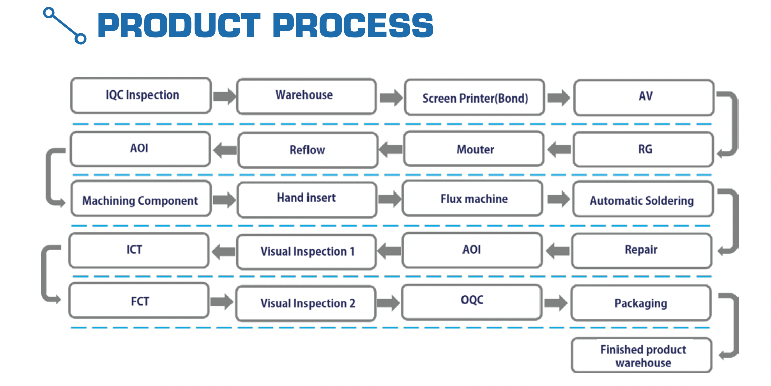
The required inspection coverage, acceptance standard, test limits, traceability level, and quality documentation should still be agreed for each OEM project. Companies evaluating manufacturing options can review SHDC’s broader PCBA Vietnam capabilities.
Conclusion
PCB Assembly Quality Control must begin before the first board enters production. A reliable plan connects approved requirements with material controls, process checkpoints, inspection methods, testing, traceability, nonconformance handling, and final lot release.
AOI, ICT, and functional testing are important, but they cannot replace revision control, incoming inspection, solder-process monitoring, first article approval, and effective corrective action.
Before selecting a PCBA supplier, US OEMs should request a product-specific control plan, review objective quality records, and verify that the supplier can demonstrate how it prevents, detects, contains, and investigates manufacturing defects.
Frequently Asked Questions
What is PCB Assembly Quality Control?
PCB assembly quality control is the set of checks used to verify that incoming materials, manufacturing processes, workmanship, electrical performance, and finished assemblies meet approved requirements.
What is the difference between PCB assembly QA and QC?
Quality assurance establishes systems and preventive processes. Quality control inspects, measures, or tests specific materials, processes, and assemblies.
What are the main PCB assembly quality checkpoints?
Typical checkpoints include IQC, solder-paste printing, SPI, placement verification, reflow control, AOI or X-ray, through-hole inspection, ICT, functional testing, and final inspection.
Is AOI enough for PCB assembly quality control?
No. AOI cannot replace incoming inspection, hidden-joint inspection, electrical testing, functional testing, process control, revision management, or traceability.
What standards are used for PCB assembly quality?
IPC-A-610 and IPC J-STD-001 are commonly referenced. The required revision, product class, customer specifications, and acceptance conditions should be agreed before production.
What quality records should a PCBA manufacturer retain?
Depending on the quality agreement, records may include material lots, process settings, inspection results, test data, firmware revision, rework history, NCR and CAPA records, and shipment traceability.
How are defective PCB assemblies handled?
Defective assemblies should be identified, segregated, documented, reviewed, assigned an approved disposition, inspected or tested after correction, and retained in the traceability history.
How can a US OEM audit PCB assembly quality control?
The OEM should review the control plan, IQC records, first article approvals, SPI and AOI controls, test-program management, traceability, rework records, nonconformance handling, and CAPA effectiveness.