
 Tiếng Việt
 日本語
日本語
For a Vietnam automotive electronics localization program, moving a purchase order is the easy part. The real work is transferring a stable PCBA process from one manufacturing site to another without losing control of materials, soldering, inspection, testing or engineering changes.
At the PCBA level, localization may include surface-mount assembly, through-hole insertion, electrical testing, functional verification, labeling and final packaging. Each activity must be rebuilt around the new factory’s equipment, work instructions and quality-control system.
SHDC’s current company profile shows an EMS operation covering component soldering, assembly, testing and final packaging. Its disclosed production infrastructure includes SMT and DIP lines, solder paste inspection, automated optical inspection, in-circuit testing and functional testing. These capabilities provide a practical foundation for OEMs evaluating automotive electronics assembly in Vietnam, although the final process must always be qualified against the actual product and customer requirements.
What Does Automotive Electronics Localization Mean at the PCBA Level?
PCBA localization means transferring the manufacturing process for an electronic assembly to a local or regional supplier while maintaining the approved product design, workmanship criteria and test performance.
It is more involved than sending Gerber files and a BOM to a new factory. A proper transfer may require:
- Rebuilding the SMT placement program
- Producing a new stencil
- Reviewing approved component sources
- Developing a new reflow profile
- Programming SPI and AOI equipment
- Creating ICT or FCT fixtures
- Correlating test results with the original manufacturing site
- Defining repair, retest and change-control procedures
Even when the PCB design remains unchanged, the process can behave differently after a transfer. A new stencil, solder paste, oven, feeder layout or test fixture may change yield and defect patterns.
For OEMs still assessing the broader supplier landscape, SHDC’s guide to automotive PCB assembly in Vietnam provides additional context. This article focuses more narrowly on transferring and validating the PCBA manufacturing process at SHDC.
Is an Automotive PCBA Project a Fit for SHDC?
The first step is to define the exact scope of the project. Automotive electronics vary widely, from compact sensor boards to mixed-technology assemblies containing connectors, relays, transformers and high-current components.
A project may involve:
- Single- or double-sided SMT assembly
- Mixed SMT and through-hole assembly
- Manual or automatic component insertion
- Wave soldering
- Visual and automated inspection
- ICT
- Product-specific functional testing
- High-voltage or aging tests
- Mechanical assembly and packaging
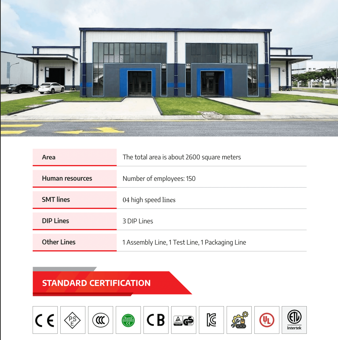
SHDC’s current profile lists approximately 2,600 square meters of factory space and around 150 employees. Its existing production scope includes four high-speed SMT lines, three DIP lines, one assembly line, one test line and one packaging line.
This combination makes SHDC relevant to both SMT-only products and mixed-technology PCBAs. It does not mean every automotive project is automatically suitable. Board dimensions, component packages, test coverage and customer-specific quality requirements still require an engineering review.
SHDC’s Current PCBA Assembly Infrastructure
SHDC’s disclosed equipment portfolio covers the main stages of PCBA manufacturing.
| Process stage | Equipment or process shown in SHDC’s profile | Role in production transfer |
|---|---|---|
| Solder paste printing | Yamaha YCP10 | Establishes solder paste deposits on SMT pads |
| Solder paste inspection | Yamaha YSi-SP 3D SPI | Identifies print-volume and alignment issues |
| SMT placement | Yamaha YSM20R and YSM10 | Places surface-mount components |
| Reflow soldering | JT N₂ reflow oven | Forms SMT solder joints |
| Optical inspection | Yamaha YSi-V 3D AOI | Checks visible placement and soldering conditions |
| Through-hole assembly | AV, insertion and hand-insert processes | Installs DIP and other leaded components |
| Wave soldering | JT wave soldering | Solders through-hole component leads |
| Electrical testing | Kyoritsu ICT F-2000 Plus | Checks selected circuit-level conditions |
| Functional testing | Product-specific test equipment | Verifies customer-defined operation |
| Final control | OQC and packaging | Confirms release and packing requirements |
The equipment list in the profile specifically shows the YSi-SP, YSi-V, Kyoritsu ICT F-2000 Plus, JT wave soldering equipment and JT N₂ reflow oven.
Yamaha’s official documentation states that the YSi-SP can evaluate solder paste volume, height, area and misalignment. Its YSi-V platform combines 2D, 3D and four-direction oblique imaging to inspect component and visible solder conditions.
A Practical Automotive PCBA Localization Roadmap
A controlled localization project should move through several defined stages rather than going directly from quotation to mass production.
1. Define the Manufacturing Scope
Before reviewing equipment, the OEM should determine which operations SHDC will perform.
The scope may cover:
- Consigned or turnkey material sourcing
- SMT assembly
- DIP and through-hole assembly
- Programming
- ICT
- FCT
- Mechanical assembly
- Labeling and serialization
- Packaging
- Finished-product storage
The OEM should also state pilot quantity, annual forecast and expected production ramp. These details influence tooling, fixture strategy and line planning.
2. Submit a Complete Data Package
An incomplete data package is one of the most common causes of quotation errors and production delays.
The project package should normally include:
- Gerber or ODB++ files
- PCB fabrication drawing
- BOM with manufacturer part numbers
- Approved component alternatives
- Pick-and-place data
- Assembly drawings
- Schematic
- PCB stack-up and surface finish
- Soldering requirements
- Firmware and programming instructions
- Test specifications
- Labeling and packaging requirements
SHDC’s PCBA manufacturer Vietnam RFQ checklist provides a more detailed reference for preparing this information.
3. Complete DFM and DFT Reviews
The transfer should include separate reviews for manufacturability and testability.
A design for manufacturing review should address:
- Board and panel dimensions
- Component spacing
- Polarity markings
- Stencil apertures
- Solder paste access
- Thermal mass
- Wave-soldering clearance
- Through-hole insertion access
A design for testability review should examine:
- ICT test points
- Power-injection points
- Ground references
- Programming access
- Communication interfaces
- Connector access
- Fixture support
- Expected measurement limits
Testability cannot be added efficiently after the PCB layout is frozen. Limited probe access may reduce ICT coverage or force the OEM to rely more heavily on functional testing.
>>>Read more: Automotive Electronics Suppliers Southeast Asia — Vietnam, Thailand & Malaysia Compared (2026)
4. Review the BOM and Component Sources
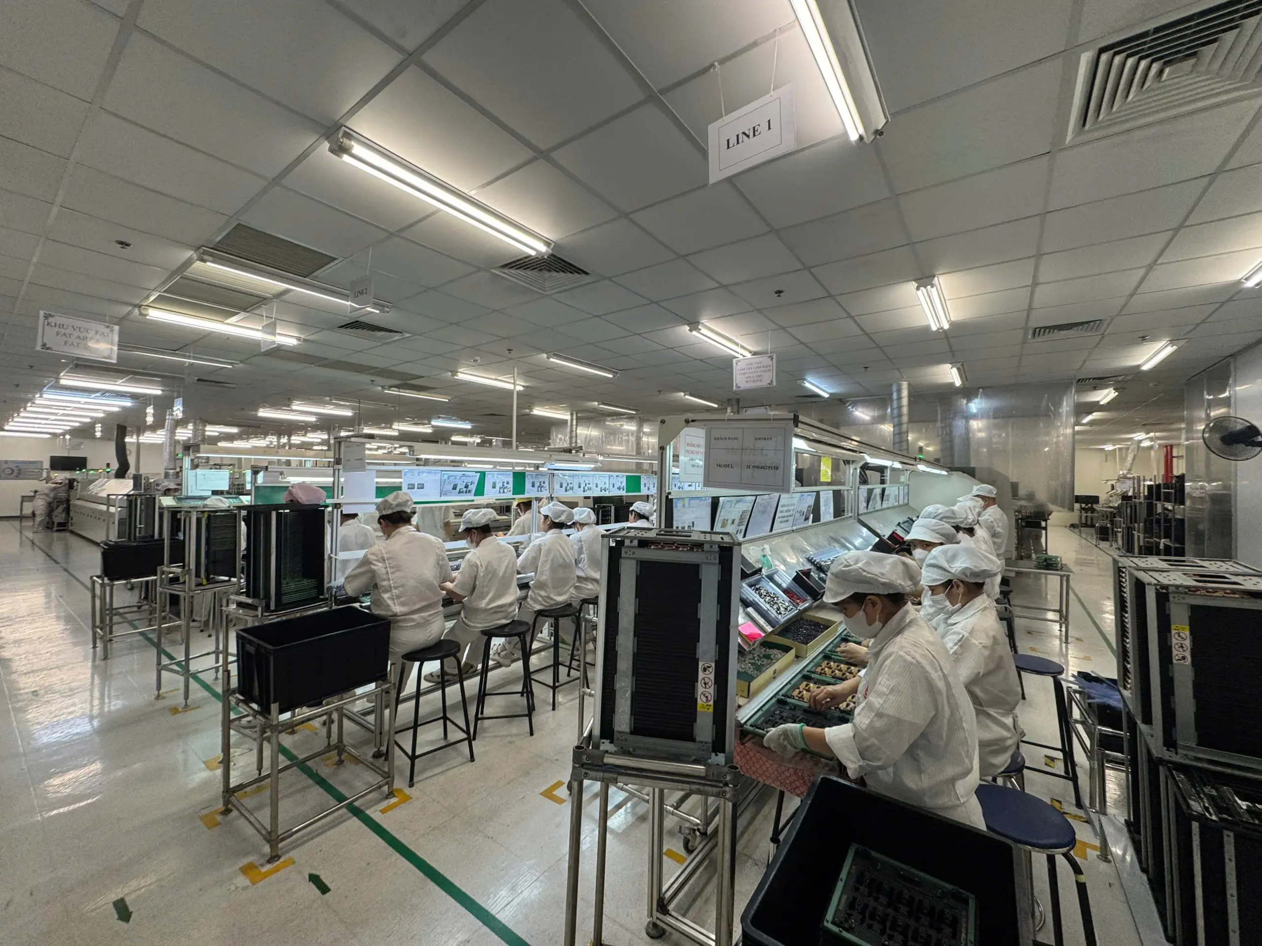
Component sourcing is part of the engineering process, not only a purchasing activity.
The BOM review should identify:
- Obsolete or allocation-sensitive parts
- Long-lead components
- Moisture-sensitive devices
- Package and termination variations
- Parts requiring customer-approved alternatives
- Customer-consigned components
- Components requiring special storage
- Counterfeit-risk items
An alternate component may have the same electrical rating but a different body size, polarity marking or thermal behavior. These differences can affect feeder setup, soldering and AOI programming.
SHDC’s profile states that the company supports electronics-material purchasing and full-process OEM services, but sourcing capability should still be confirmed against the specific BOM.
5. Develop the Manufacturing Process
Once the data and BOM are approved, the factory can begin building the production process.
Typical activities include:
- Stencil fabrication
- Solder paste selection
- Printer setup
- SPI programming
- Feeder preparation
- Placement-program development
- Reflow profiling
- AOI-program development
- DIP insertion planning
- Wave-soldering setup
- Repair-instruction development
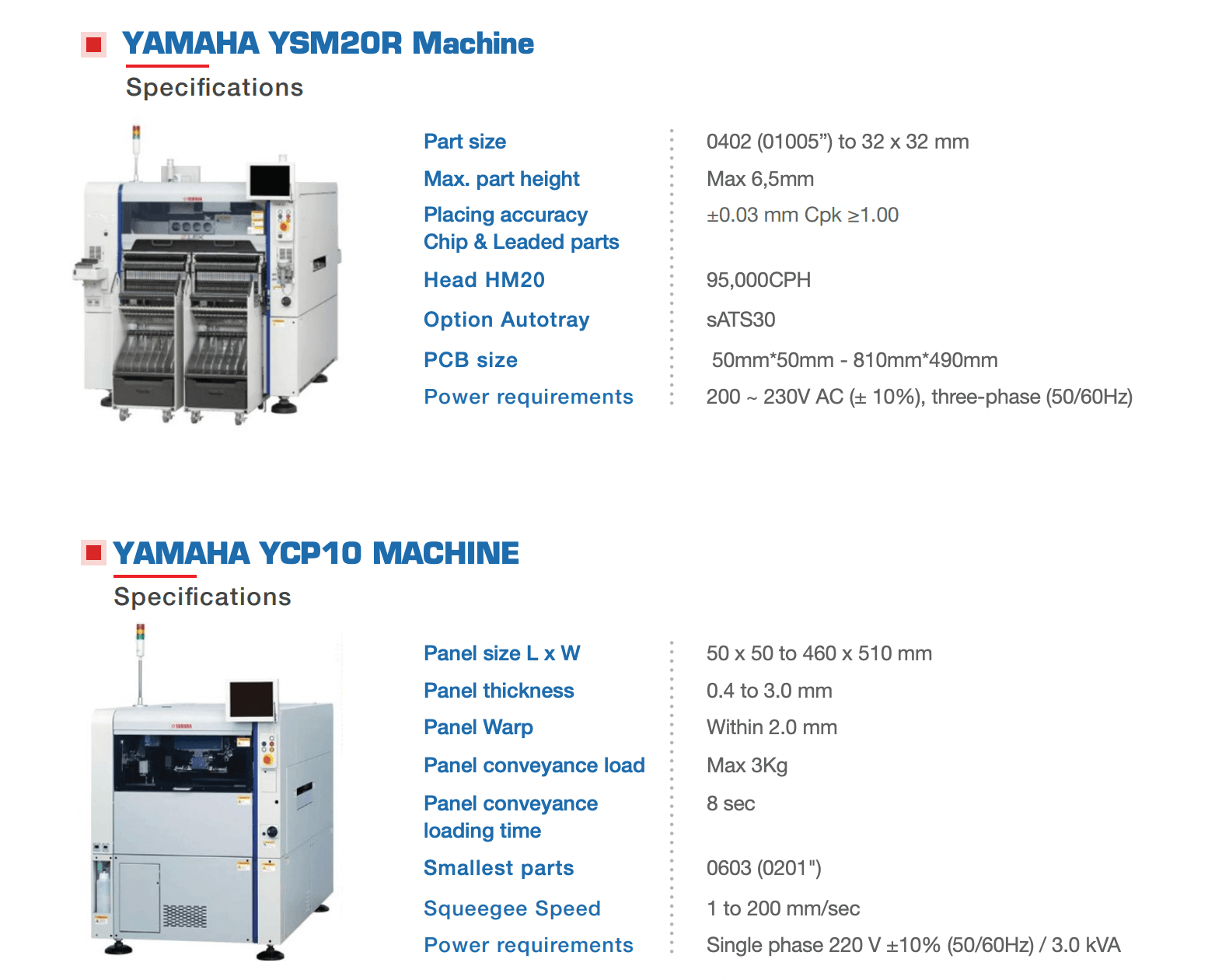
The Yamaha YCP10 documented in SHDC’s profile is designed for large PCB formats and varied stencil frames. Yamaha lists an applicable PCB range from 50 × 50 mm to 510 × 460 mm for the standard machine specification. The actual board must still pass DFM and tooling review.
6. Develop ICT and FCT Requirements
ICT and FCT should be designed around defined risks rather than added as generic end-of-line steps.
For ICT, the OEM may need to provide:
- Netlist
- Test-point coordinates
- Expected component values
- Guarding requirements
- Coverage targets
- Fixture ownership requirements
- Retest limits
For FCT, the required information may include:
- Connector pinout
- Power conditions
- Input stimuli
- Expected outputs
- Communication protocol
- Firmware revision
- Timing limits
- Fault-response requirements
- Pass/fail criteria
ICT and FCT are complementary. ICT can help isolate opens, shorts and selected component-level conditions, while FCT verifies whether the assembled board performs its intended function. SHDC’s guide to ICT vs. functional testing explains this distinction in greater detail.
7. Run a Pilot Build
A pilot build is where assumptions are replaced by production data.
The pilot should be used to:
- Verify manufacturing files
- Confirm stencil performance
- Review SPI results
- Validate component placement
- Establish the reflow profile
- Debug the AOI program
- Review SMT and wave-soldering defects
- Correlate ICT and FCT fixtures
- Confirm test limits
- Measure first-pass yield
- Identify rework requirements
For higher-risk projects, a structured production validation testing phase can help confirm that the line, fixtures and documentation are ready for repeatable volume production.
8. Approve the Production Release
Mass production should begin only after the OEM and manufacturer agree on the approved process baseline.
The release package may include:
- Approved pilot samples
- Reflow-profile record
- SPI and AOI criteria
- ICT and FCT program revisions
- Fixture identification
- Work instructions
- Rework and retest procedures
- Packaging approval
- Change-notification requirements
This is especially important when the transferred product already has an established quality history at another site. The new process should be correlated with the original acceptance and test requirements.
SMT and DIP Capabilities for Mixed-Technology Automotive PCBAs
Automotive electronics frequently use both surface-mount and through-hole components.
SMT is suitable for dense circuitry, small passive components, ICs and compact modules. Through-hole assembly is often retained for parts that need mechanical strength, higher current capacity or larger physical interfaces, including:
- Connectors
- Relays
- Transformers
- Large capacitors
- Power components
- Mechanical switches
SHDC’s profile shows automatic insertion, AV plug-in equipment, hand insertion, a flux machine and JT wave soldering. This supports evaluation of products that cannot be completed on an SMT line alone.
The choice between the two technologies should be made during product and process review. SHDC’s comparison of SMT processing vs. through-hole assembly provides further guidance on the trade-offs.
Typical through-hole risks include incorrect polarity, incomplete insertion, bent leads, insufficient hole fill, solder bridges, non-wetting and solder skips. These conditions require controls that differ from those used for SMT printing and placement.
Inspection and Testing at SHDC
A reliable localization program needs several verification layers.
3D SPI
Solder paste inspection occurs before component placement. It helps identify insufficient paste, excessive deposits and positional errors while the board can still be cleaned and reprinted.
3D AOI
AOI is typically used after reflow to evaluate visible assembly conditions such as component presence, orientation, offset and certain solder defects.
AOI cannot confirm firmware, full electrical integrity or hidden BGA joints. It should be one part of a wider PCB assembly quality control plan.
ICT
The Kyoritsu ICT F-2000 Plus shown in SHDC’s profile can support circuit-level testing, but actual fault coverage depends on PCB test access, fixture design and the approved program.
FCT and Additional Tests
SHDC’s equipment portfolio also shows:
- Functional testing
- High-voltage testing
- A/V testing
- Aging testing
The tests applied to a project depend on the board design and customer-approved test plan. The presence of equipment should not be interpreted as confirmation that every PCBA automatically receives every test.
Quality Documentation and Automotive Requirements
Automotive PCBA localization requires stronger documentation than a simple commercial assembly order.
The OEM should define expectations for:
- BOM and drawing revision control
- Firmware revision
- Material-lot traceability
- Test-program control
- Fixture identification
- Calibration
- Rework history
- Retest requirements
- Engineering-change approval
- Data-retention period
The latest IPC J-STD-001J and IPC-A-610J address soldered-assembly process requirements and post-assembly acceptability. They are frequently used together, but the applicable class and customer criteria must be specified for each program. (IPC J-STD-001J and IPC-A-610J) (electronics.org)
Automotive customers may also require APQP, control-plan or PPAP deliverables. AIAG’s APQP 3rd Edition includes expanded guidance on sourcing, change management, traceability and risk-mitigation planning. (AIAG)
Requirements can vary by customer. The IATF Global Oversight website maintains separate customer-specific requirements for participating automotive OEMs, so the applicable documents should be reviewed during contract and project planning. (IATF Global Oversight)
The current SHDC profile does not provide enough information to claim that every project is automatically covered by IATF 16949, PPAP support or full serial-level traceability. These requirements should be confirmed against the manufacturing site and project scope before sourcing approval.
Current Capacity and the Planned Phase 2 Factory
SHDC’s current factory scope consists of four SMT lines, three DIP lines and dedicated assembly, test and packaging lines.
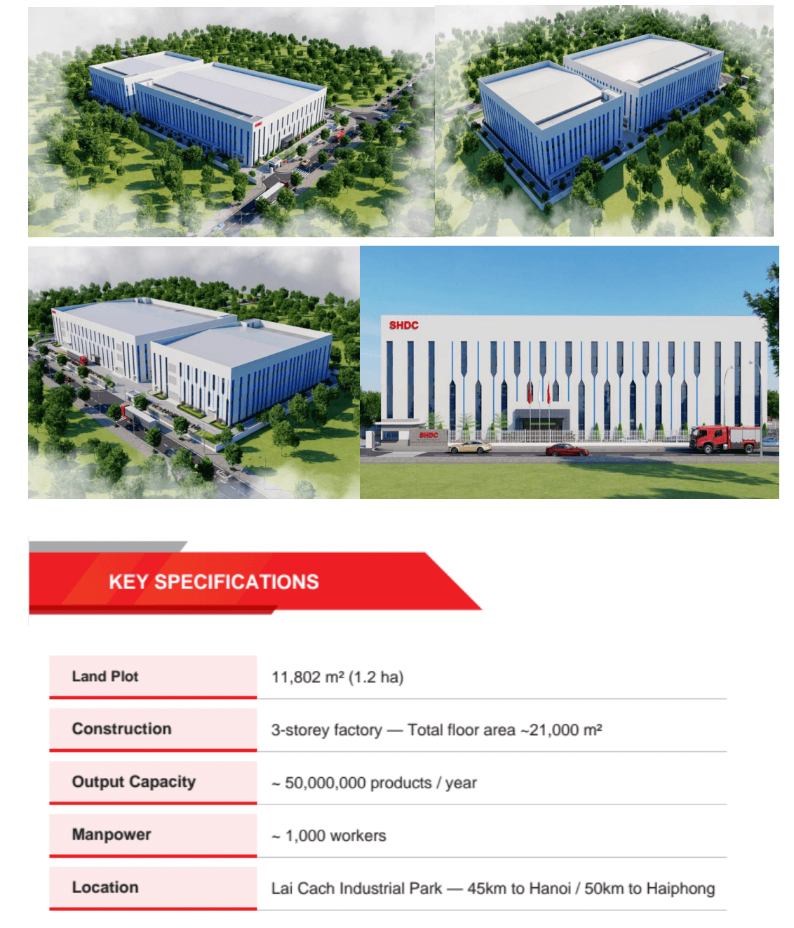
The company profile separately describes a planned Phase 2 facility at Lai Cach Industrial Park, with a target date of March 2027. The stated objectives include 28 lines, approximately 1,000 employees and annual output of 50 million units. These figures refer to planned expansion and should not be presented as current operating capacity.
Automotive PCBA Localization Checklist
Before releasing a project, confirm that:
- The manufacturing scope is clearly defined.
- PCB, BOM and firmware revisions are aligned.
- Approved component alternatives are documented.
- DFM and DFT reviews are complete.
- SMT and DIP requirements are confirmed.
- SPI and AOI criteria are defined.
- Reflow and wave-soldering processes are validated.
- ICT test access and fixture ownership are agreed.
- FCT specifications and pass/fail limits are available.
- Pilot-build acceptance criteria are approved.
- Rework and retest rules are documented.
- Traceability requirements are defined.
- Customer-specific automotive requirements are reviewed.
- Production release is based on approved pilot data.
Read more: Automotive PCBA in Vietnam: How SHDC Uses AOI, ICT and FCT for Assembly Verification
Conclusion: Localize the PCBA Process, Not Just the Purchase Order
A successful Vietnam automotive electronics localization project depends on transferring a controlled manufacturing system—not simply changing the supplier name on the purchase order.
SHDC’s disclosed SMT, DIP, SPI, AOI, ICT, FCT and backend assembly capabilities provide a practical platform for evaluating automotive PCBA programs. The final decision should still be based on product-specific DFM and DFT reviews, pilot-build results, test coverage and customer-approved quality requirements.
OEMs should send SHDC a complete manufacturing package, including PCB files, BOM, schematic, test specifications and expected production volume, so the factory can evaluate both assembly feasibility and testing needs before quotation and pilot production.
Frequently Asked Questions
What is Vietnam automotive electronics localization?
It is the transfer of automotive electronics manufacturing activities—such as PCBA assembly, inspection, testing and packaging—to a supplier in Vietnam while maintaining the approved product design and quality requirements.
Can SHDC support both SMT and DIP PCB assemblies?
SHDC’s current company profile lists four high-speed SMT lines and three DIP lines, along with separate assembly, testing and packaging lines. The suitability of a specific project still requires an engineering review.
What SMT equipment is shown in SHDC’s profile?
The profile lists a Yamaha YCP10 solder paste printer, YSi-SP 3D SPI, Yamaha YSM20R and YSM10 placement machines, a JT N₂ reflow oven and Yamaha YSi-V 3D AOI.
What PCBA testing can SHDC support?
The disclosed equipment includes Kyoritsu ICT F-2000 Plus, functional testing, high-voltage testing, A/V testing and aging testing. The exact test route must be defined for each product.
Does every automotive PCBA require AOI, ICT and FCT?
No. The required combination depends on product risk, design for testability, production volume and customer-specific requirements.
Why is a pilot build necessary?
A pilot build validates manufacturing data, stencil performance, placement, soldering, inspection programs, fixtures and test limits before volume production begins.
Can SHDC source automotive electronic components?
SHDC states that it supports electronic-material purchasing, but sourcing capability, approved manufacturers and alternative parts must be reviewed against the specific BOM.
Is SHDC’s Phase 2 factory already operating?
No. The company profile identifies Phase 2 as a planned facility with a target date of March 2027.
>>>Read more: Automotive PCBA Vietnam | Trusted Non-China Manufacturer for USA
