
 Tiếng Việt
 日本語
日本語
A working prototype does not always mean a product is ready for manufacturing. In PCBA production, small design, BOM, assembly, or testing issues can create delays, rework, low yield, and unexpected cost when the project moves into pilot run or mass production. This DFM checklist helps electronics OEMs review the most important areas before sending files to an EMS partner, requesting a quote, or starting production.
What Is a DFM Checklist for PCBA Manufacturing?

A DFM checklist is a practical review tool used to confirm whether a PCB design can be manufactured, assembled, inspected, tested, and delivered consistently. For PCBA projects, it usually covers PCB layout, Gerber files, BOM, SMT assembly, DIP or through-hole components, testing, documentation, packaging, and production readiness.
Unlike a general DFM for electronics manufacturing guide, this checklist is more action-oriented. It focuses on what OEMs should review before production starts.
For OEM teams, the goal is simple: identify manufacturability risks early, before they become engineering changes, sourcing problems, test failures, or production delays.
When Should OEMs Use a DFM Checklist?
OEMs should use a DFM checklist before major production decisions are locked. The best timing is before PCB fabrication, before ordering mass-production components, before requesting a PCB assembly quote, and before moving from prototype to pilot production.
A checklist is especially useful when:
- The product is moving from prototype to mass production
- The PCBA includes both SMT and through-hole components
- The BOM includes long-lead or custom components
- The board requires ICT, FCT, AOI, or special inspection
- The product has enclosure, cable, or final assembly requirements
- The OEM is changing suppliers or moving production offshore
- Previous builds had quality, yield, or delivery issues
A DFM checklist should not be treated as a final formality. It should be part of the development and production-readiness process.
Quick DFM Checklist Summary for PCBA Projects
| DFM Area | What OEMs Should Review | Why It Matters |
|---|---|---|
| PCB Layout | Spacing, pads, fiducials, board edge clearance, panelization | Reduces assembly and handling risks |
| BOM | MPN, lifecycle, alternatives, lead time, sourcing notes | Prevents procurement delays |
| Gerber Files | Copper layers, solder mask, silkscreen, drill files, paste layers | Supports accurate PCB fabrication |
| Pick-and-Place File | X/Y coordinates, rotation, polarity, side placement | Improves SMT placement accuracy |
| SMT Assembly | Paste printing, component spacing, reflow compatibility | Reduces soldering defects |
| DIP / Through-Hole | Hole size, lead length, soldering method, mechanical strength | Supports stable assembly |
| Testing | AOI, ICT, FCT, test points, pass/fail criteria | Improves quality control |
| Documentation | Assembly drawing, test procedure, packaging instructions | Reduces communication errors |
| Packaging | ESD protection, labels, carton specs, finished goods handling | Protects product quality after assembly |
PCB Layout DFM Checklist
PCB layout is one of the most important parts of PCBA manufacturability. A board can function electrically but still be difficult to assemble, inspect, or test. Before production, OEMs should review the layout from a manufacturing perspective.
Board Dimensions and Panelization
Start by checking whether the PCB size is suitable for the production line. Very small, thin, flexible, or irregularly shaped boards may require special carriers, tooling, or handling methods.
OEMs should review:
- Is the PCB size compatible with assembly equipment?
- Is the panelization method defined?
- Are V-cuts, breakaway tabs, or routing methods suitable?
- Are components placed too close to board edges?
- Is there enough clearance for depanelization?
- Are tooling holes or fiducials included where required?
- Will the panel remain stable during SMT assembly?
Panelization should be reviewed before fabrication, not after boards are already produced. Poor panel design can slow down assembly and increase handling risks.
Component Spacing and Placement
Component placement affects soldering, inspection, rework, and final assembly. Dense layouts may save space but can create process issues if spacing is too tight.
Review these points:
- Are components spaced properly for automated assembly?
- Are tall components placed away from areas that need machine access?
- Are heat-sensitive components away from high-temperature zones?
- Are connectors easy to access during assembly and testing?
- Are polarized components clearly marked?
- Are components placed away from mounting holes and enclosure features?
- Are heavy components supported properly?
Good placement helps reduce defects and improves the efficiency of the SMT assembly process.
Pad Design and Solderability
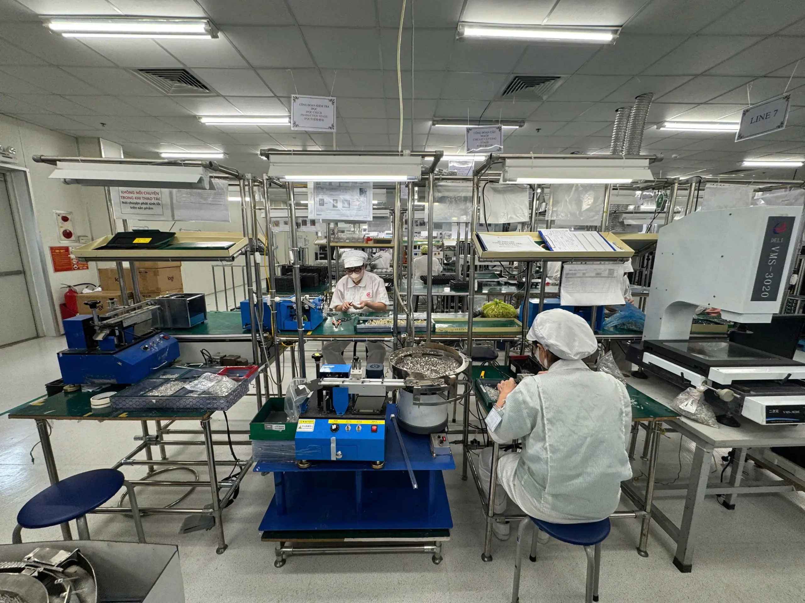
Incorrect land patterns are a common source of soldering problems. Pads that are too large, too small, or unbalanced can lead to tombstoning, insufficient solder, bridging, or weak joints.
OEMs should check:
- Are land patterns correct for each component package?
- Are pads balanced for small passive components?
- Are thermal pads designed to reduce voiding?
- Is solder mask clearance appropriate?
- Are fine-pitch components reviewed carefully?
- Are exposed pads and heat sinks designed for reliable soldering?
- Are there any special stencil requirements?
Many common PCB assembly defects can be reduced by reviewing pad design early.
Fiducials and Alignment Marks
Fiducials help automated equipment align the board accurately. Missing or poorly placed fiducials can affect pick-and-place accuracy, especially on dense PCBs or boards with fine-pitch components.
Checklist:
- Are global fiducials included?
- Are local fiducials used for fine-pitch ICs or BGAs?
- Are fiducials unobstructed?
- Are fiducials placed consistently across the panel?
- Is there enough clearance around each fiducial?
- Are fiducials present on both sides for double-sided assembly?
BOM Checklist for PCBA Manufacturing
The BOM is not just a purchasing document. It directly affects quotation accuracy, sourcing risk, production planning, assembly process, and delivery timeline.
Complete Component Information
A complete BOM should include clear information for every part. Missing or vague data can delay quotation and procurement.
Review whether the BOM includes:
- Manufacturer part number
- Component description
- Package size
- Quantity per board
- Reference designators
- Approved suppliers
- Alternative parts
- DNI, DNP, or optional parts
- Special handling notes
If the BOM only includes generic descriptions, the EMS partner may need additional time to confirm parts, pricing, and availability.
Component Availability and Lifecycle
Component availability can become a major production risk. A design that uses obsolete, restricted, or long-lead components may be difficult to scale.
OEMs should check:
- Are any components obsolete or near end-of-life?
- Are long-lead components identified?
- Are approved alternatives listed?
- Are there supplier restrictions?
- Are MOQ and lead time risks understood?
- Are critical components available for pilot and mass production?
- Are there parts that require customer approval before substitution?
This is especially important for OEMs using offshore or electronics manufacturing outsourcing, where sourcing timelines and logistics must be planned carefully.
Component Polarity and Special Requirements
Some components need additional documentation to avoid assembly errors.
Review whether the BOM and assembly files clearly identify:
- Diode orientation
- LED polarity
- Electrolytic capacitor polarity
- IC pin 1 orientation
- Connector orientation
- Moisture-sensitive components
- Programmed ICs
- Firmware loading requirements
- Custom labels or markings
Polarity and programming mistakes can create expensive failures if they are discovered late in production.
Gerber, Pick-and-Place, and Manufacturing File Checklist
Even a strong PCB design can create problems if manufacturing files are incomplete or inconsistent. OEMs should prepare a complete file package before requesting quotation or production.
Gerber File Checklist
Gerber files should clearly communicate the PCB fabrication requirements.
Check the following:
- Are all copper layers included?
- Are solder mask layers included?
- Are paste layers included?
- Are silkscreen layers included?
- Are drill files complete?
- Is the board outline clear?
- Are layer names easy to understand?
- Are impedance or special stack-up requirements documented?
- Are surface finish and PCB material requirements specified?
- Are revision numbers included?
A clear Gerber package helps avoid confusion between PCB fabrication and assembly teams.
Pick-and-Place File Checklist
The pick-and-place file is critical for SMT programming. Errors in coordinates or rotation can cause component misplacement.
Review:
- Are X/Y coordinates accurate?
- Are component rotations correct?
- Are top and bottom placements separated?
- Are reference designators aligned with the BOM?
- Are units clearly defined?
- Are polarity-sensitive parts verified?
- Are no-load components removed or marked clearly?
For double-sided boards, side identification must be especially clear.
Assembly Drawing Checklist
Assembly drawings help production teams understand special instructions that are not obvious from Gerber or BOM files.
Check whether the assembly drawing includes:
- Component locations
- Polarity markings
- Mechanical notes
- Manual assembly steps
- Connector orientation
- Critical components
- Labeling instructions
- Revision control
Clear assembly drawings reduce the risk of interpretation errors between OEM and EMS teams.
SMT Assembly DFM Checklist
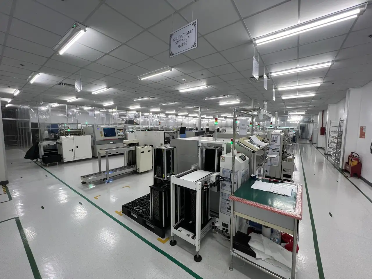
SMT is efficient and widely used in modern PCBA production, but it requires careful control of layout, paste printing, placement, and reflow.
Solder Paste Printing
Solder paste printing is one of the first process steps that can affect downstream quality.
Review:
- Are stencil requirements defined?
- Are fine-pitch components suitable for paste printing?
- Are large thermal pads segmented if needed?
- Are small passives placed to reduce tombstoning risk?
- Are aperture reductions needed for dense areas?
- Is paste volume suitable for the component package?
Poor paste design can lead to bridging, insufficient solder, solder balls, or voiding.
Pick-and-Place Compatibility
Not all SMT components are equally easy to place. Some parts may need special feeders, trays, or manual handling.
OEMs should check:
- Are SMT components available in tape-and-reel format?
- Are odd-form components identified?
- Are very small components reviewed for placement accuracy?
- Are heavy SMT parts supported properly?
- Are components placed with enough nozzle clearance?
- Are bottom-side parts suitable for double-sided reflow?
A good SMT production line depends on accurate files, stable components, and manufacturable placement.
Reflow Soldering
Reflow compatibility should be reviewed before production. Components with different thermal requirements may create process challenges.
Checklist:
- Are all components compatible with the planned reflow profile?
- Are temperature-sensitive components identified?
- Are large copper areas balanced?
- Are heavy components placed appropriately?
- Are double-sided reflow requirements clear?
- Are heat-sensitive connectors or plastic parts protected?
If a board includes both SMT and through-hole components, the sequence should be planned carefully. OEMs can also compare SMT vs through-hole requirements before finalizing the assembly process.
DIP and Through-Hole Assembly Checklist
Through-hole assembly is still important for connectors, transformers, switches, large capacitors, and components that need mechanical strength.
Through-Hole Component Design
Check:
- Are hole sizes correct?
- Are lead lengths suitable?
- Are component bodies stable after insertion?
- Are tall parts positioned safely?
- Are keep-out areas defined?
- Are mechanical parts aligned with the enclosure?
- Are heavy parts supported with additional fixation if needed?
Soldering Method
Through-hole components may require wave soldering, selective soldering, or manual soldering. The design should match the intended process.
Review:
- Is the board suitable for wave soldering?
- Are manual soldering steps minimized?
- Are heat-sensitive parts protected?
- Are solder joints accessible for inspection?
- Are components placed in a direction suitable for solder flow?
- Are masking or fixtures required?
For mixed-technology boards, OEMs should also understand wave soldering vs reflow soldering because each process has different design and quality requirements.
Testing and Inspection Checklist
Testing and inspection should be designed into the PCBA, not added after the board is complete.
AOI Inspection Checklist
Automated optical inspection helps detect placement and soldering issues, but the board must be designed so critical areas are visible.
Check:
- Can AOI inspect all critical components?
- Are component markings visible?
- Are solder joints accessible for optical inspection?
- Are similar-looking components clearly identified?
- Are polarity markings visible?
- Are components blocked by tall neighboring parts?
AOI is valuable, but it should be supported by clear markings, accessible solder joints, and good assembly documentation.
ICT Checklist
In-circuit testing can help verify electrical connections and component-level issues, but it requires accessible test points.
Review:
- Are test points included?
- Are test pads large enough?
- Are test points away from tall components?
- Is spacing suitable for test probes?
- Are power and ground nets accessible?
- Are key signals available for testing?
- Is the board suitable for a test fixture?
Poor test access can increase test time and reduce defect detection.
FCT Checklist
Functional testing verifies whether the PCBA performs as intended in operating conditions.
OEMs should define:
- Functional test procedure
- Pass/fail criteria
- Required firmware or programming steps
- Test fixture requirements
- Cables, loads, or external devices needed
- Test time per unit
- Data recording requirements
- Failure handling procedure
A clear FCT plan helps the EMS partner prepare test fixtures and production flow before the pilot run.
Mechanical Assembly and Box Build Checklist
For products that require enclosure assembly, cable routing, labeling, or final product integration, DFM should extend beyond bare PCBA.
Review:
- Does the PCBA fit the enclosure?
- Are mounting holes correct?
- Are connectors aligned with housing openings?
- Are screws, standoffs, and clips positioned properly?
- Is cable routing clear?
- Are heatsinks, thermal pads, or insulation materials required?
- Are labels and serial numbers defined?
- Are final assembly instructions complete?
OEMs that need more than board assembly should consider a partner with box build assembly services or full service EMS in Vietnam, depending on the project scope.
Packaging and Shipping Checklist
PCBA quality can still be affected after assembly if packaging and handling are not defined.
Check:
- Is ESD protection required?
- Are individual bags, trays, or foam inserts needed?
- Are labels and barcodes defined?
- Are carton specifications confirmed?
- Are finished goods inspection requirements clear?
- Are customer-specific packaging rules documented?
- Are export packaging requirements considered?
- Are storage and handling conditions defined?
Packaging should be reviewed before mass production, especially for products shipped internationally.
Production Readiness Checklist Before Pilot Run or Mass Production
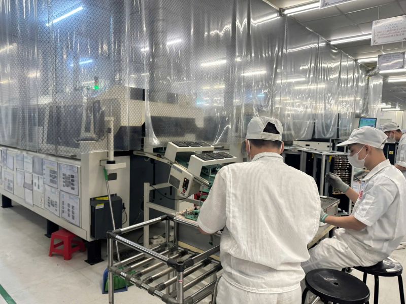
Before starting pilot production or mass production, OEMs should confirm that the project is ready from design, sourcing, process, quality, and logistics perspectives.
Review:
- Are all design files approved?
- Is the BOM frozen?
- Are critical components available?
- Are approved alternatives confirmed?
- Are SMT and DIP process steps defined?
- Are test fixtures ready?
- Are inspection standards approved?
- Are packaging requirements finalized?
- Is the pilot run quantity defined?
- Is the production schedule confirmed?
- Are quality records and traceability requirements agreed?
- Is the failure analysis process clear?
A structured Production Readiness Checklist helps OEMs confirm that the project is ready before scaling to volume production.
Common Red Flags Found During DFM Review
Incomplete BOM
A BOM without manufacturer part numbers, approved alternatives, or clear reference designators can delay quotation and procurement.
Missing Test Points
No test points or poor test access can make ICT difficult and increase reliance on manual inspection or functional testing only.
Components Too Close to Board Edges
Components near board edges may be damaged during handling, depanelization, or fixture use.
Incorrect Component Orientation
Wrong polarity, rotation, or pin 1 marking can cause assembly failures and rework.
Prototype Design Not Ready for Production
A hand-built prototype may work, but the same design may not be suitable for automated production. This is one of the most common issues found during DFM review.
Late Engineering Changes
Late changes can lead to new files, updated BOMs, sourcing delays, and revalidation. A clear process for Engineering Change Orders helps OEMs control risk when design changes are necessary.
Questions OEMs Should Ask Their EMS Partner During DFM Review
A DFM checklist works best when OEMs and EMS teams discuss manufacturability together. Before production, ask:
- Do you see any PCB layout risks?
- Are all components suitable for automated assembly?
- Are there any BOM sourcing risks?
- Do we need to adjust the panelization design?
- Are there any SMT or through-hole process concerns?
- Are test points sufficient for ICT or FCT?
- What inspection method do you recommend?
- What issues should be validated during pilot production?
- What changes could improve yield or reduce rework?
- Are there any packaging or handling risks?
These questions help OEMs evaluate not only the design, but also the capability and communication quality of the manufacturing partner. This is important during EMS provider selection, especially for U.S. OEMs working with offshore partners.
How SHDC Supports OEMs With PCBA Manufacturing Readiness

SHDC supports OEM customers with electronics manufacturing services, including SMT, DIP, assembly, testing, and packaging. For PCBA projects, SHDC’s production process can support key manufacturing stages such as IQC inspection, SMT processing, reflow, AOI, component insertion, soldering, ICT, FCT, visual inspection, OQC, packaging, and finished goods handling.
This process-oriented capability is important for DFM because manufacturability is not only about the PCB design. It is also about how the design moves through real production steps, including material control, assembly, inspection, testing, and final delivery.
SHDC also has experience with PCBA applications such as power-related products, chargers, water purifier boards, computer mouse boards, petrol-related electronics, and automotive-related PCBA. For OEMs preparing electronic products for pilot build or mass production, early manufacturing review can help reduce avoidable risks.
For U.S. companies considering electronics manufacturing in Vietnam, SHDC can support projects from manufacturing review to PCBA production, testing, final assembly, and packaging.
Final Thoughts
A DFM checklist helps electronics OEMs reduce avoidable PCBA production risks before they become costly problems. The checklist should cover PCB layout, BOM, manufacturing files, SMT assembly, through-hole assembly, inspection, testing, documentation, packaging, and production readiness.
For OEMs preparing for pilot production or mass production, DFM should be completed early. The best results come when the OEM and EMS partner review the design together, clarify requirements, and resolve manufacturability issues before components are purchased and production lines are scheduled.
If you are preparing a PCBA project for production, SHDC can help review your requirements and support the process from SMT and DIP assembly to testing, final assembly, and packaging.
FAQs About DFM Checklist for PCBA Manufacturing
What is a DFM checklist for PCBA manufacturing?
A DFM checklist for PCBA manufacturing is a practical review list used to check whether a PCB design, BOM, assembly process, testing plan, documentation, and packaging requirements are ready for production.
When should OEMs use a DFM checklist?
OEMs should use a DFM checklist before PCB fabrication, quotation, prototype revision, pilot production, or mass production. It is most useful before the design and BOM are locked.
What files are needed for a PCBA DFM review?
Common files include Gerber files, BOM, pick-and-place file, assembly drawing, PCB specifications, test requirements, firmware instructions, mechanical files, and packaging requirements.
Why is BOM review important in DFM?
BOM review helps identify missing part numbers, obsolete components, long-lead parts, sourcing risks, incorrect package sizes, and approved alternatives before production begins.
What is included in a PCB assembly checklist?
A PCB assembly checklist usually includes PCB layout review, component placement, soldering requirements, SMT and DIP process checks, inspection, testing, documentation, and packaging requirements.
Can an EMS partner help with a DFM checklist?
Yes. An EMS partner can review the checklist from a manufacturing perspective and provide feedback on PCB assembly, component sourcing, SMT and DIP process planning, testing, inspection, and production flow.
